1960-1962 Chryslers |
|
The dash mounted turn signal switch on the 1960-62 Chryslers is quite an unusual thing, a marvel of engineering,
and a little bit complicated.
In a previous article we looked at the switch itself, now we take a look at the other bits and pieces. This might be useful if you have to troubleshoot the horn system.
??What?? The horn system is connected to the turn signal system??? Read on and you'll find that it is.
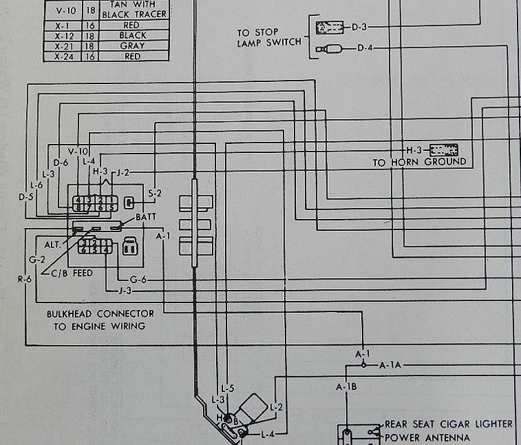
 The factory service manual details horns in the "Electrical And Instruments" section (pages 8-51 and 8-88), with the wiring diagram (see below) on pages 8-74 and 8-78. Since the 1930's, horn circuits have used a relay due to the significant amperage required by the horns, and our system is no different.
The relay has a "B" (battery) terminal, "S" (ground) terminal, and "H" (horn) terminal. If you bypass the relay with a jumper from the battery to the horns and they work, the problem is not with the horns. If you run a jumper from the relay "S" (ground) terminal to a known good ground (how about the battery post) and horns work, then the problem is not with the horns or the relay. Most likely the problem is with "H-3" wire on the wiring diagram. And now we go in search of ground, which is a bit complicated for 1960 – 1962.

|
The H-3 wire runs from the horn relay to the firewall junction block. Click the diagram to enlarge,
and you'll see H-3 runs to the #2 spot on the junction block.
|
|
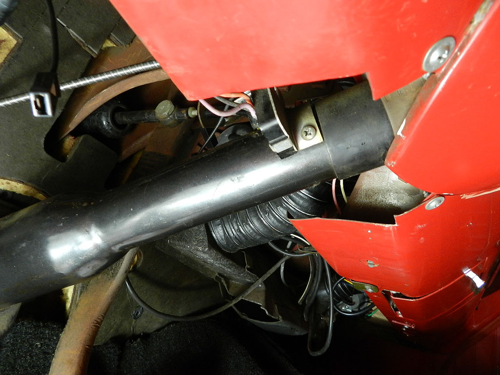
From the firewall connector, H-3 runs
|
|
|
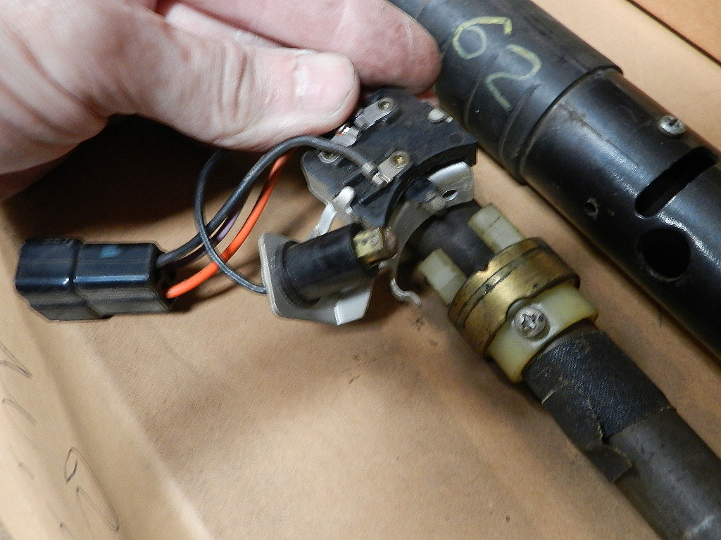
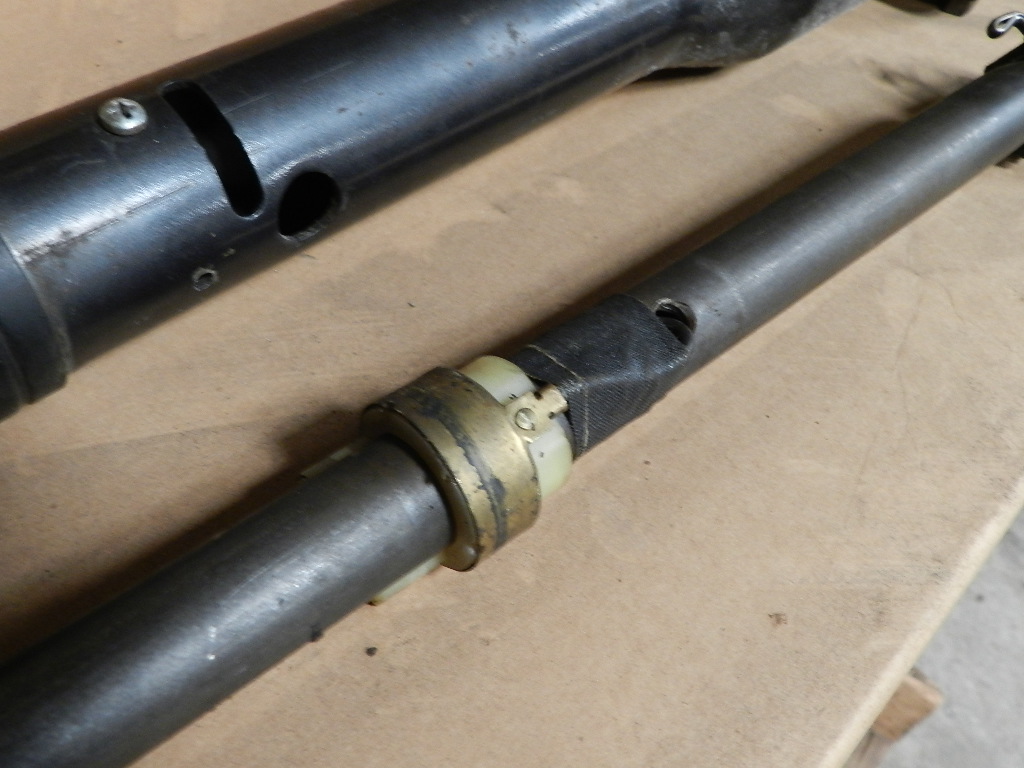
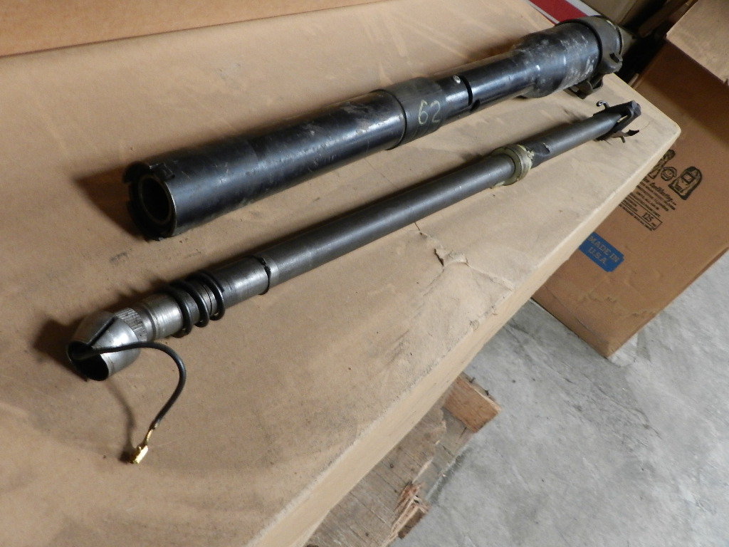
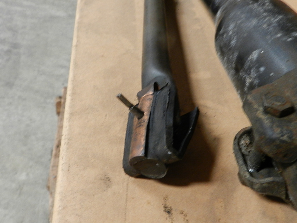
H-3 connects to the gizmo and by way of a wheel, it connects to a copper collar on the steering shaft. From the collar, another wire is connected, runs up inside the steering shaft and out to the horn switch. The next four pictures illustrate those pieces in more detail. |
|

|
|
|
|
The wire exiting the top of the steering shaft connects to the horn switch. The horn switch grounds to the steering shaft. The steering shaft needs to find ground at the steering box, and it does so with a thin copper strip. If your check for ground reveals all connections are good between H-3 at the horn relay and the horn switch at the steering wheel, it could be that the copper strip needs to be replaced. We recently did that on a 64, video here. As you can see, there is a lot to check for those innocent two words "horn ground" shown on the wiring diagram. Crimeny, an awful lot of work just to blow the horn..... Back |
|