|
Save That Dimmer
by John Grady
Jan, 2025
I was working on the headlight switch for the 57C and found the dimmer
 for the instrument lights was broken. I set to work on a
repair. While the following is specific to the 57 C switch, the same
ideas work on other similar switches.
Do not throw away any early switch because the dimmer isn't working;
these switches can be saved. A common cause for dimmer failure is
from a short to ground on the orange wires, usually at a bulb socket.
This short will cause excessive current to flow. Although the switch
has a built-in 20 amp breaker, this will not protect the dimmer.
In
my case, it looks like the dimmer had been set toward bright and the
excessive current burned the resistance wire just before the end.
This is just before the point where the 12 volt feeds in (also the
full on click at end of turn range).
The
resistance coil is embedded at the bottom in some kind of ceramic
cement but usually you can remove the small burned segment going
toward the brass. It may break off, high heat seems to make the wire
brittle.
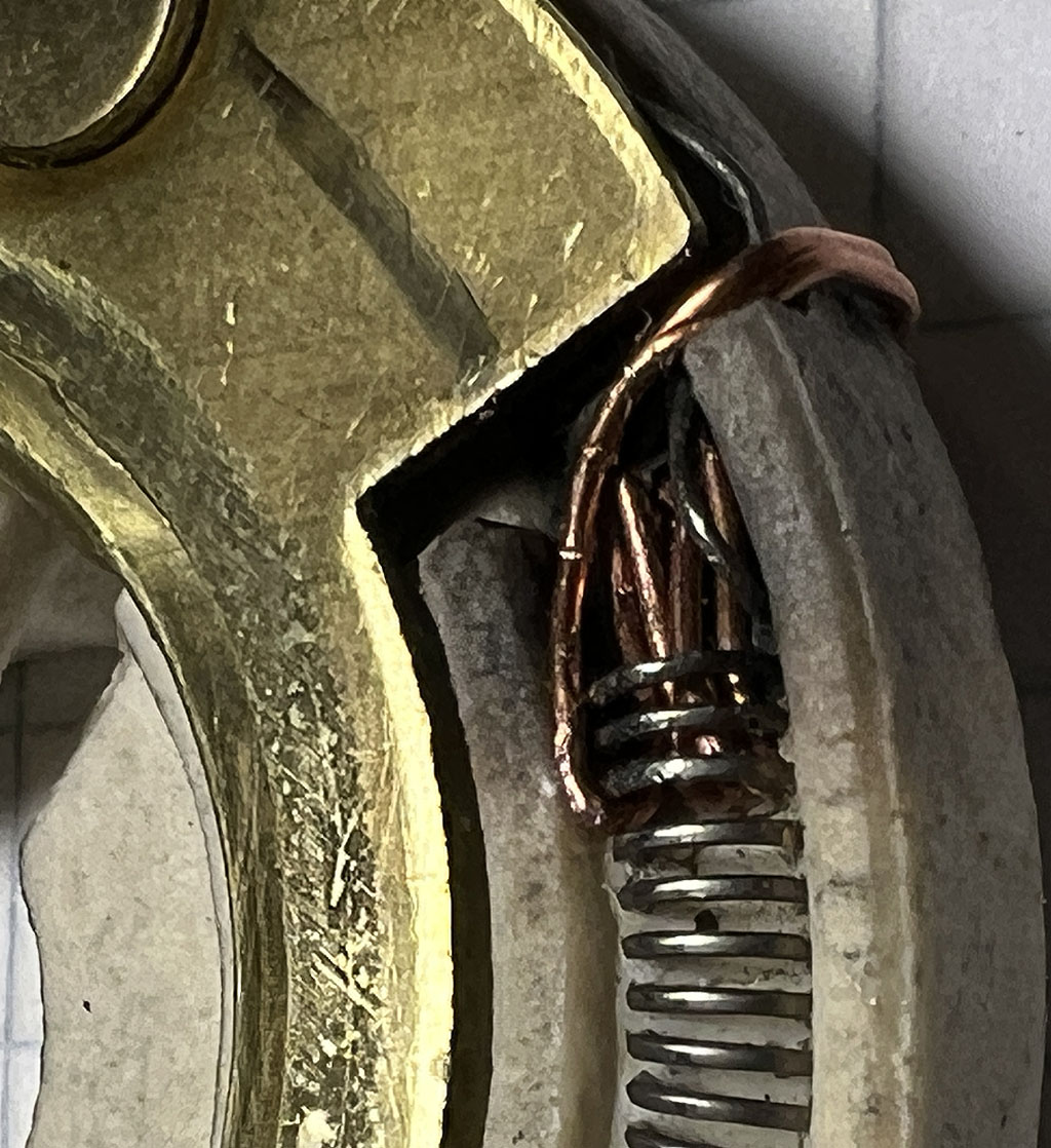
 Try not to disturb the winding that is still OK. The repair
idea is to put a U loop of copper around and through the last 2-3
turns of the resistance wire. Dress it carefully so the scraping
contact on top won't hit it or cause a bump. The repair strand is
from 12 stranded building wire. It goes to the brass. In this case it
went toward inside then outside.
Now there is a pocket left where the burned part was removed. Since
solder will not “take“ to the resistance wire and we want
to fill that pocket, we make a filler mesh of the same strand folded
tight about 4 times and 1/4” - 3/8” long. Stuff this into
the resistance wire coil so the end is in the space. This will serve
as a scaffold for the solder to tin and helps contact too. Solder
shrinks a bit as it hardens which will grab the resistance wire and
give us a good bite. Scrape the resistance wire with a box cutter to
get it shiny at the end coils. Now
set it up vertically, use a good soldering iron (I use a 250 watt
gun) and solder all this together. Try to leave the top of the solder
level with the brass. You want to make a smooth ramp and not leave a
big lump of solder although you can file to shape later. My switch
had a notch in the ceramic and I ran U ends out soldered to edge of
brass. Do not get solder under brass as it will tilt it.

|

|

Check the resistance wire with an ohmmeter. To the end is 10 ohms and at the brass end it is zero
ohms.
Reassemble.
The spring goes in the ceramic pocket (I put it on wrong side of
pronged plate first time).
I
noticed that two of the 3 copper rivets support the sliding center
contact and I connected them together outside (black sleeved wire).
Wow no flickering!

The
short in my switch was at the pod the switch is in. The wire from the
rheostat to dash lights was scraped and touched the inside of switch
pod.
To prevent this from happening again I added a 3A fuse. On a 300F this
fuse might be a 5 amp due to EL lighting . It is easy on this C with
the external wire feeding the rheostat. On an F you might have to put
the fuse in the orange leads splice together to one wire onto dimmer
terminal.
While
doing this project, I discovered the drawing of the headlight switch
in the 57 factory shop manual has an error. Talk about maximum
confusion! The 57 manual is below on the left. See how the feed to the headlight switch comes to the top where the 20 amp breaker is located. This is wrong. The 58 manual is on the right. The feed comes to the B terminal. This is correct.

The big takeaway is the 20 A circuit breaker with big stud
on it is not the power in or out. It is only live when headlights are
on and cannot be used as a 12 Volt tap or for a battery feed.
The
two sockets marked "IN" are exactly the same connection. They are the
instrument feed and tailights. The two sockets near the metal
stamped "P" and "IG" are front park lights only and possibly the ignition
key light on other models. The 300C does not have a light at the key.
"B"
is battery feed. "A" is accessory feed constant 12 Volt for the brake light switch, the clock,
the dome light and the map light. I believe
there is a 20 Amp breaker inside the switch between the "B" and "A"
terminals. Headlights are fed from the "H" socket.
A final thought on all this. As an option, you can rewire the orange dash light feed into the tail light
connection which will bypass the dimmer and give you full on dash lighting.


|