|
Vacuum Advance |
|||||
|
I got into this subject on a J K ram distributor. There are two ways to advance timing; vacuum advance and mechanical advance. The vacuum advance is accomplished by a can attached to the outside of the distributor body. The mechanical is done by two spring loaded weights inside the distributor which move outwards with increasing RPM. For the J, the factory specified an initial timing of 15 degrees BTDC. Other Mopar engines in 1963 were 10 degrees which means the vacuum advance for the J is unique to the J.
Having the correct operating vacuum advance is important. You can expect the original diaphragms in the vacuum can are more or less shot. What to do if you need a new vacuum advance? You could try
to get your old advance rebuilt or you could try a modern unit.
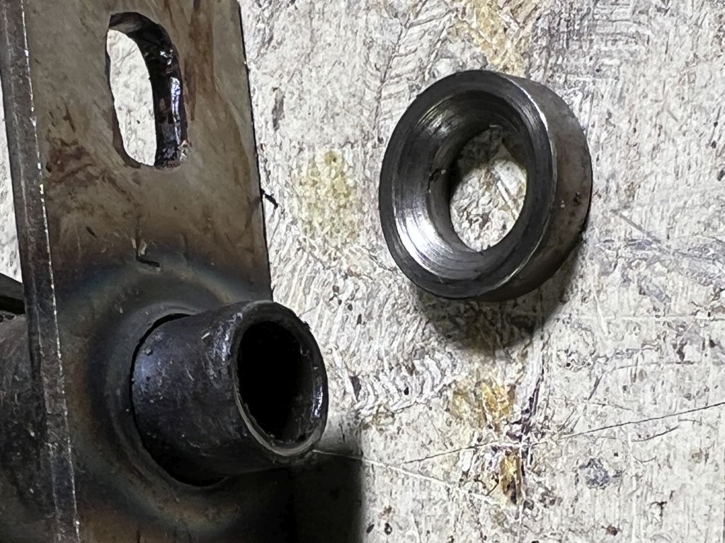
I measured the difference between this new advance and the one from the J. I figured out that I needed to stop the flag .040" sooner. I took .040" brass wire and I added it to the flag. I made sure it stays there with dab of weatherstrip adhesive. By adding this brass wire, I have changed the max advance on the new unit from 11 to 8 degrees.
If you were to look inside the vacuum advance unit, there is a large spring. It sits against the vacuum diaphragm and controls the initiation of vacuum advance. Sometimes you will find washers with the spring. This is like a pre-load. With washers, you increase the initial starting vacuum required to move it. The spring's stiffness, or spring constant, determines how quickly the advance increases with more vacuum, although this has no impact on total advance.
Don't lose this critical spacer. The open cone goes down toward engine. It sometimes sticks to cam bottom and rolls under bench. 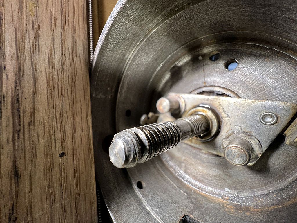
Looking good, spacer is in its location. 
Ready to advance. Note that light spring weight has a bronze bushing. This weight moves a lot. 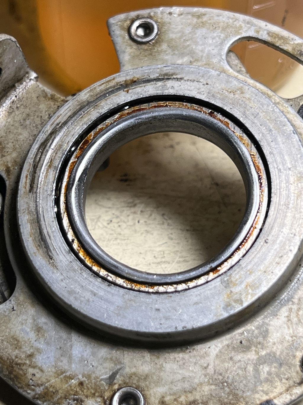
The vacuum advance plate is mounted on a real ball bearing, not pins and sliding brass feet used on single point distributors. Make sure this bearing moves freely. Lubricate with 75 W.
Since I was deep into the distributor, I did other things.
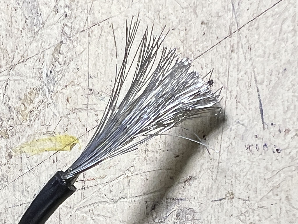
Ultra flex silicone wire (Amazon) 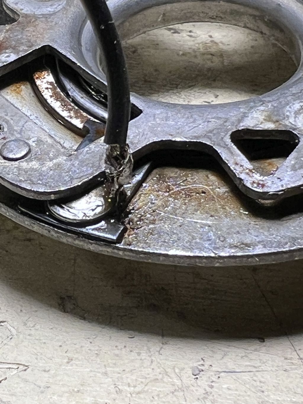
New longer ground jumper folded up leg. No solder blobs allowed 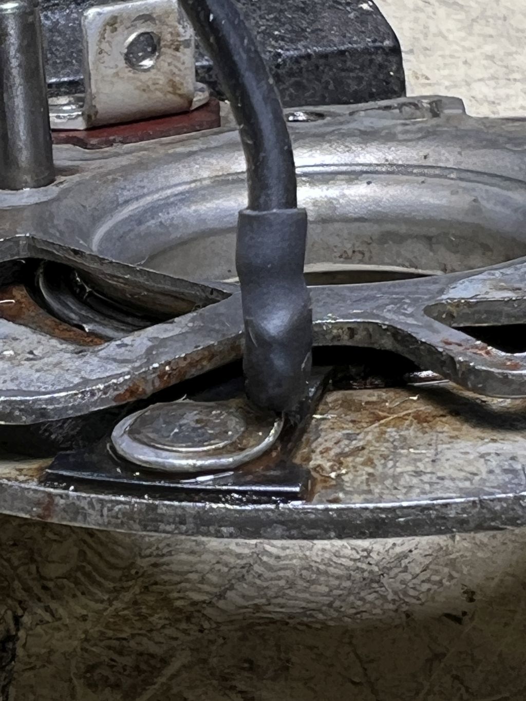
Heat shrink just right length, prevents break off at attachment by grabbing outer insulation 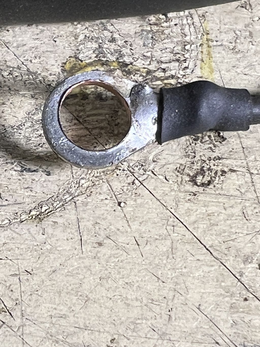
Have to enlarge small #8 eyelet with reamer to fit over #10 stud . #10 eyelet is too big. Even #8 crimp part is shortened about 1/2 cut off -- wire off inlet terminal post cannot stick up 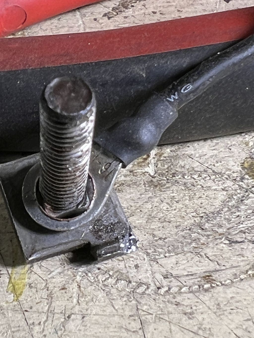
On terminal, one ear of factory part removed so new terminal sits at 45 degrees. Also need to file the Bakelite insulator to allow that 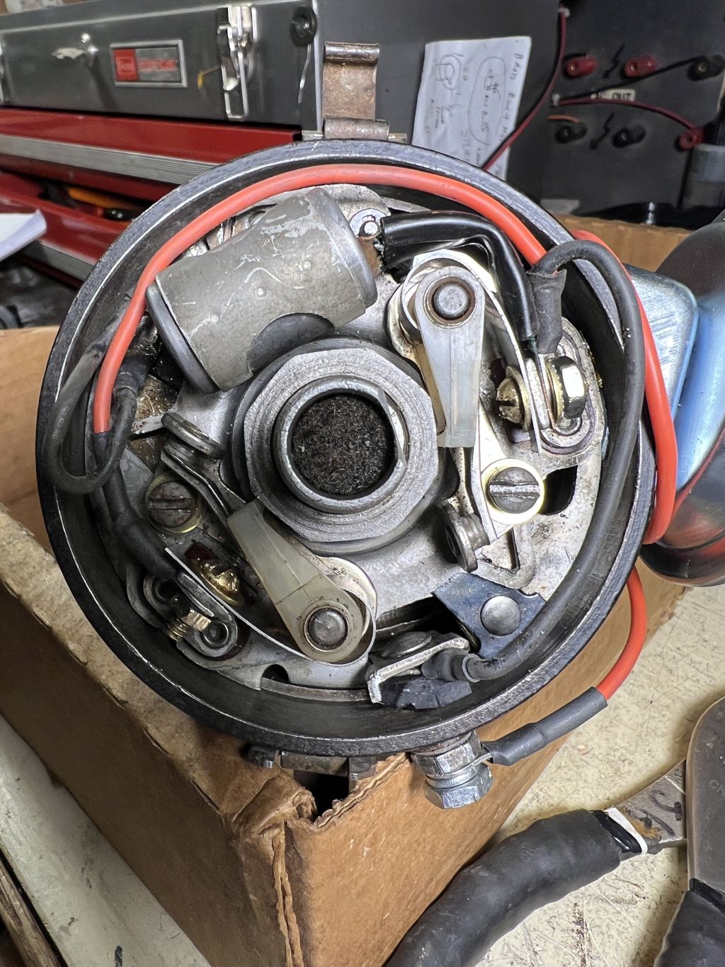
Beautiful!! Note long ground jumper loop, wires and point arrangement at mount flag, brass washer under clamp screw so gap does not change as you tighten points Although this picture shows a brass round head screw, the correct screw to use is a 6/32 hex head so you can tighten them easily with a small wrench. I did not have those hex head screws when I took this picture. |
|||||


. Lite one flies in low rpm, big guy stops it from doing much more. Lubricate with 75 W on these.
note light spring weight has a brass bush in weight . she moves a lot .")