|
57-59 Magnetic Gauges
Feb 1, 2025
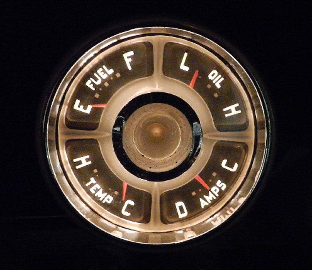
The dash
gauges 1957-59 are "magnetic gauges". The 1960 & newer
are "thermal gauges." We have an explanation below about
how they operate and how they are different.
If you go on the web and search for 57 - 59 sending units, you find some that
say they fit but make no mention of the ohm range. You find some that
say they fit and have 10-70 ohm range. You find some that say they
fit and have a 15-200 ohm range. You want the 15-200 ohm sender.
Now that we have the numbers the gauge wants, let's see what numbers the sending unit gives us. With the float arm sitting on the bottom stop, the sender is 200 ohms and the needle is slightly above E. Here, on the bottom stop, the sender is at maximum resistance. Relocating the float or bending the sending unit arm won't improve accuracy, but why would you need to? Having a little reserve in the tank is a great thing to avoid running out of gas. While a perfect sending unit would have 240 ohms at E, a sending unit with 200 is very much OK. John
continued his investigation. He set up a sender installed in the
tank. He found that at the bottom stop, the sender float is 1/2"
off of the tank floor, providing a reserve of 1 or 2 gallons. This is
OK.
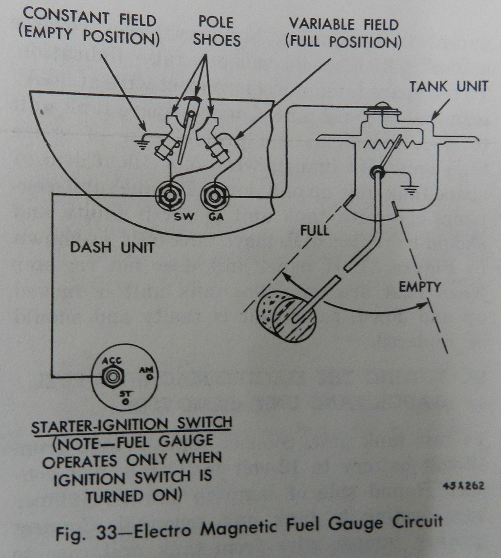
How It Works
The coils are wired so they each get the same generator output (11 to 14 volts). If generator output increases, both coils get equally stronger and no matter where the needle is on the dial, it does not change position. For this reason, no voltage regulator is needed. One coil is wired for full strength all the time. The second coil is weaker. It actually has a little less volts due to the drop at its ground end in the tank resistor. To compensate, the gauge is designed such that the needle rests on the F mark at float full up. If you were to ground the tank lead, the needle goes beyond F. Going beyond the E or the F is not a good thing as the needle can stick off scale. As the float drops more ohms are added to the second coil. Current decreases, magnetic strength decreases. The full strength coil begins to win the tug of war and the needle moves toward E. At 200 ohms, float full down, the needle is just above E. Should your needle go off scale below E, look for a broken wire or intermittent contact sender. John had a gauge where the needle stuck below E, you can read about his repair here. For those that like numbers and test results, John measured coil volts. With the input held at 13.6 volts, at F the coil is seeing 10.5 volts (a drop of 3.1 volts due to 30 ohm resistance from the sender). At E the coil sees 4.5 volts due to the 200 ohm resistance.
How It Works
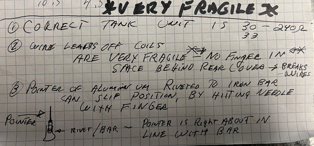
John Grady writes: On my gauge, a previous owner had
broken the very fine wire off of the S coil. He had been
holding the gauge with a finger over the back sheet metal — (easy
to do). These gauges are extremely fragile things. When out of their
gauge pod, there is no case around it for protection. Carry it wrong and you break
it. Carry it by grabbing the front and back faces with no fingers in the space in between.
Another thing to be careful of;
any bumping of the needle can get it misaligned to magnet bar. There is a
tiny rivet in there that gets loose.
John Grady's math for magnetic gauges 
Those fine wires inside the gauges 
|