|
1963-1964
AM-FM Delco Chrysler Radios
The
1963-64 Chrysler AM-FM radios were produced by Delco, and were the
first factory radios offered by Chrysler with the FM band. The FM
band was monaural on these radios. FM multiplex stereo broadcasting
was introduced in 1961, but stereo FM was not offered on Chrysler
radios until later in the 1960's as car radio receiver technology
advanced.
The
modern FM band from 88MHz-108MHz was established in the USA around
1946. Radio manufacturers began including the band on their higher
end sets, but most early circuit designs had less sensitivity and
selectivity than modern sets. Relatively few stations occupied the
band in the early years (compared to the crowded dials of today).
While FM offered the potential of superior sound quality compared to
AM, with a broadcast frequency response typically 20Hz-15,000Hz along
with static-free reception, the signal strength would vary
dramatically depending on the receiver antenna location, height, and
distance from the transmitter. Consequently, given the limitations
of the receiver technology of the day, the small size of the car
radio chassis, and the rapidly changing signal strength in the mobile
environment, it was impractical to offer the FM band in car radios.
By
the early 1960's, through the use of transistors and more advanced
circuit designs, it became viable to offer the FM band on car radios.
Effective with production starting in January, 1963, this AM-FM
radio became available as the premium radio offering on the Chrysler
line.
In
both 1963 and 1964 the radio was only available with the front fender
mounted manual antenna. Why not offer it with the optional power
antenna? After all, the radio was available on the Imperial in 1964
with a power antenna. Actually, it had nothing to do with manual vs.
power, it had to do with the location of the antenna. On the
Chrysler, the optional power antenna was located on the rear fender
and therefore required a long antenna lead-in cable. On the AM band,
an antenna trimmer on the radio had to be adjusted by the dealer to
compensate for the long cable, which was part of the tuned input
circuit. The AM-FM set included a trimmer located on the underside
of the radio to perform this adjustment for the AM band, but there
was no such adjustment for the FM band. I guess the concern was that
the long lead-in cable might adversely affect FM reception to the
point that customer complaints would result. I'm not convinced it's
a big deal, as my experience with bench testing the radio is that the
FM sensitivity is excellent and is sufficient to offset potential
problems with the long cable. However, such an installation with a
power antenna in a 300J or 300K would be incorrect for concours
judging.
That
said, for those considering a radio upgrade to their 300J or 300K by
simply installing one of these AM-FM sets in the bezel opening that
is currently occupied by their Bendix AM 5 button or 7 button set,
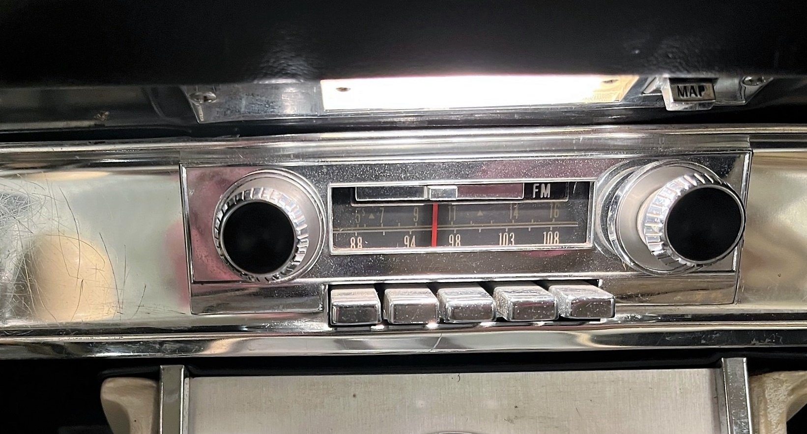
think again! The Delco AM-FM radio has a physically smaller front
fascia than the Bendix sets do, and the radio knobs are spaced closer
together. A special dash bezel was produced for these radios, and
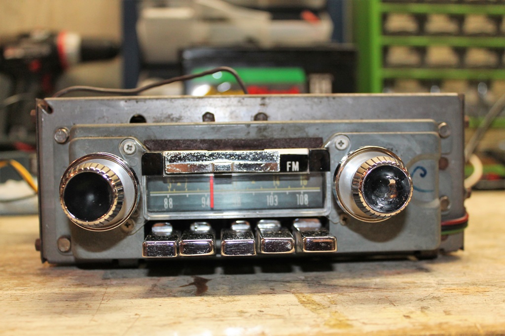
you will need that part in order to install the radio. Here is a
photo of the special bezel:
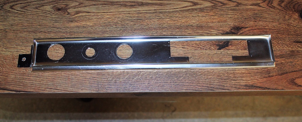 This particular example was removed from a New Yorker Salon, where this radio, A/C and Auto-Pilot were standard equipment. Auto-Pilot was not available on the 300J or 300K with the Firepower 390 ram engine, and A/C was optional of course, and so you'll need a bezel with suitable cutouts for the options on your car. They are fairly rare. Note that there are not separate cutouts for the radio knobs. That is because these radios use a special chrome plated escutcheon that is mounted on top of the aluminum dash bezel but under the radio knobs. Here is a photo of that item: 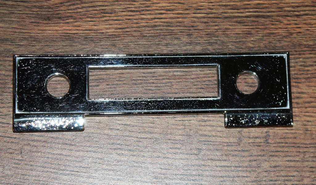 These radios featured excellent reception on both bands. The AM band performance is comparable to the Bendix AM radios offered the same year, although subjectively I think the sound quality is a bit better on the Bendix sets. The FM band reception was close to state of the art for the day, but the FM fidelity was really no better than the AM band and nowhere near that of high end home hi-fi or stereo sets of the period. Do not expect hi-fi FM sound from these radios. We'll discuss that below. These radios were similar in style to their GM “wonderbar” counterparts sans the search-tune capability. The circuit, however, was unique to the Chrysler model. You might read on the internet that one should NEVER use a speaker less than 8 ohms with these Delco sets, and you'll see that on reputable radio repair and restoration sites. That is INCORRECT. They are talking about the GM radios, which used special 10 ohm speakers. The Chrysler versions of these sets were designed to be used with the 4 ohm Mopar speakers used on the AM only radios. Both the 1963 and 1964 versions appear cosmetically identical from the front as installed in the car, but the physical chassis and circuits are different for each year. We will now examine each model year offering separately. Please refer to our introductory page about radios for general information and servicing tips here: https://chrysler300club.com/tech/radio/1.html 1963
The controls should be the same as the Bendix AM sets. 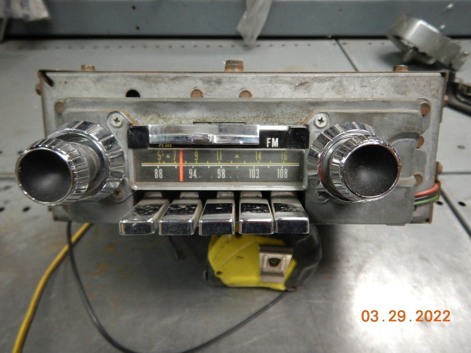 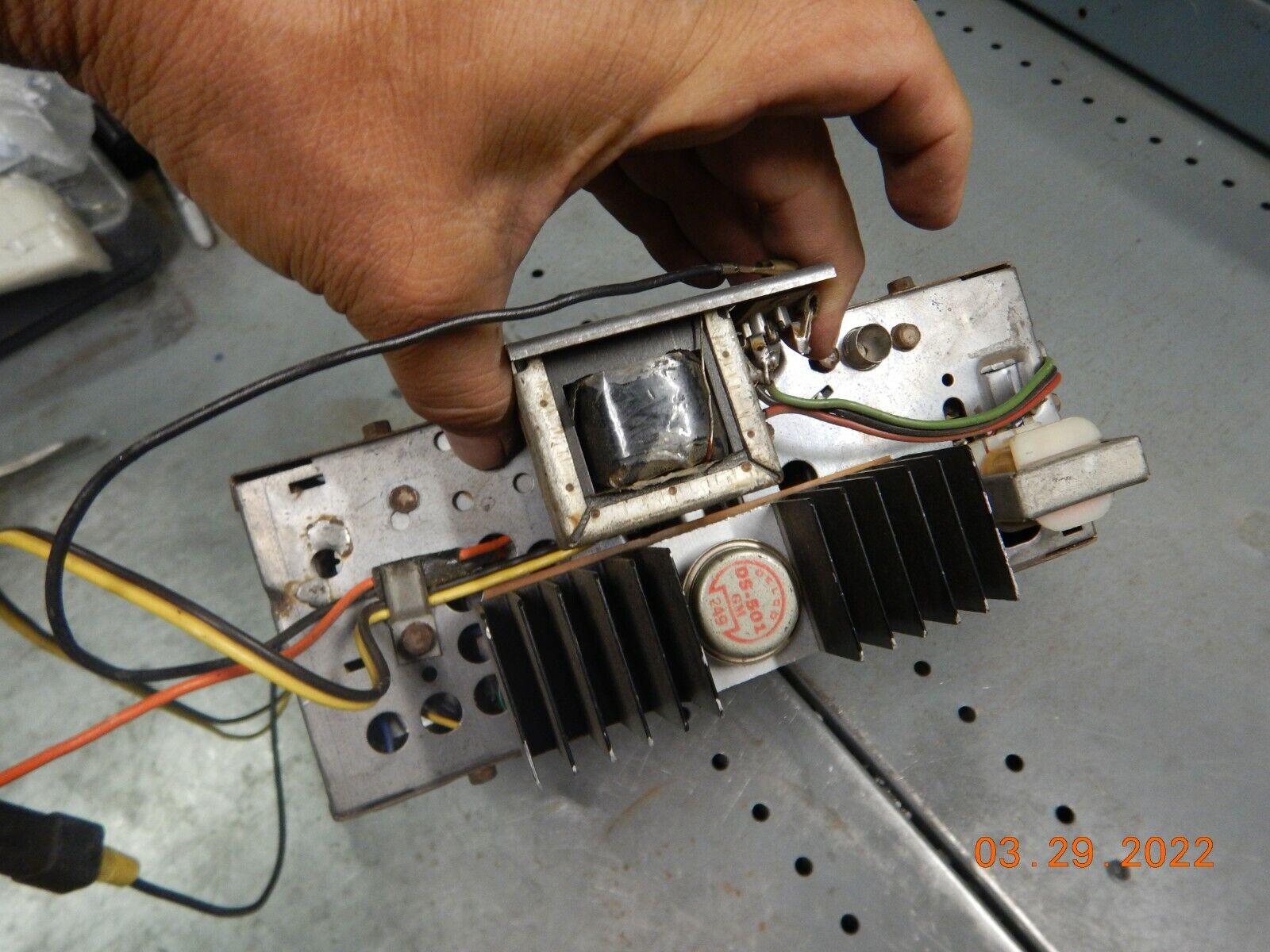 1964
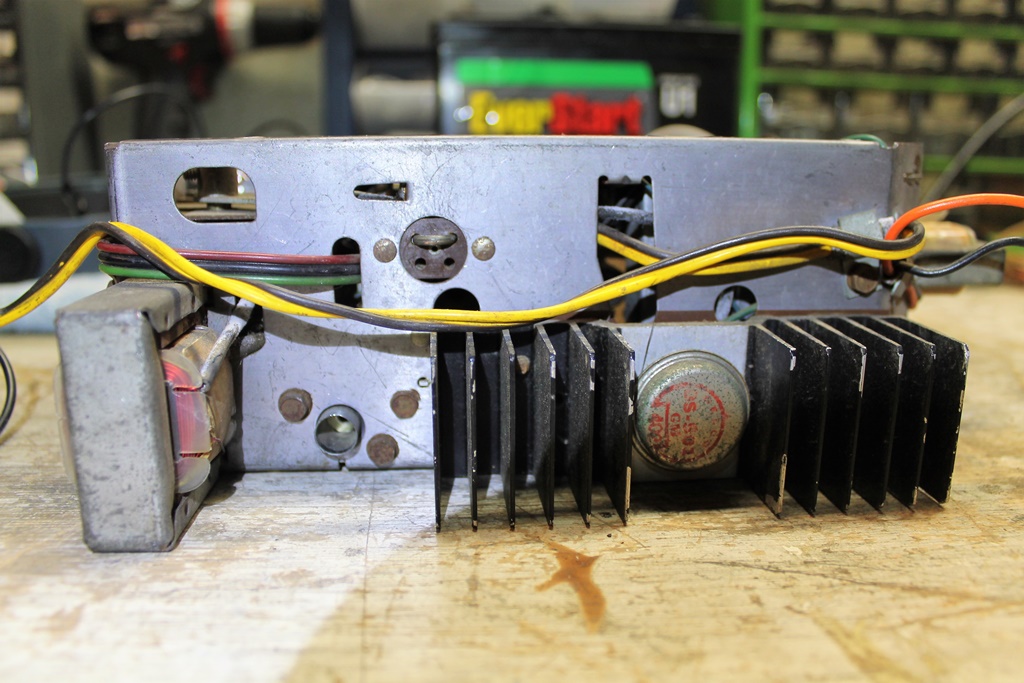
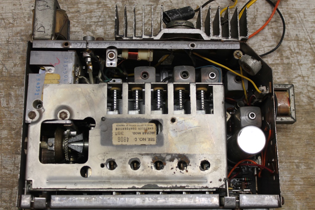
The 1964 chassis had some rearranging of the external physical
components. Here is a photo of the back of the chassis. Note the
positioning of the jumper in the rear speaker socket which is
required when only a front speaker is connected.
For both years, the radio internals are crowded and challenging to
work on. If you are a DIY car guy, but a radio novice, this would
not be the easiest set to learn on. But I like a good challenge and
decided to work on one of these as my second car radio project ever
attempted. The unit is a 1964 set removed from a parts car that
hadn't been powered up in perhaps 40 or 50 years.
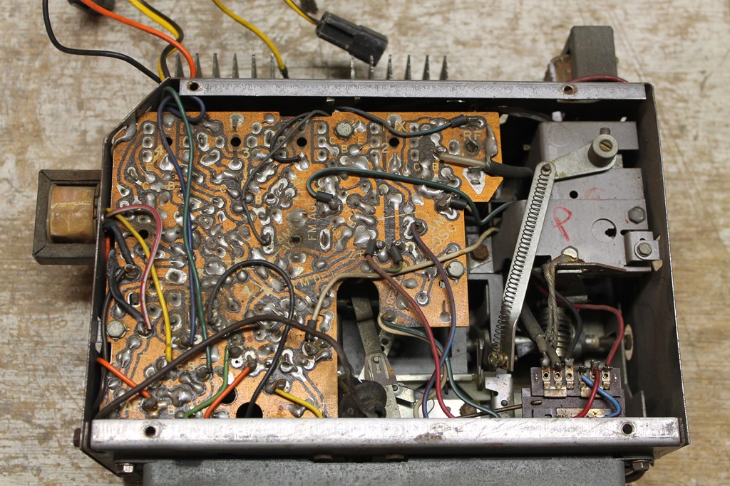
The complete underside of the circuit board is accessible. The tuner
is enclosed on the upper right and is best left undisturbed.
Removing the circuit board can be risky because it is very old.
Unsoldering all the connections can result in broken traces.
However, it is possible to parallel in new e-caps for 8 of the 9
total from above. You absolutely need a circuit trace diagram to do
this, and the Delco service manual has one. The Sam's Photofact has
photos of the physical layout with components keyed to the schematic.
The results will look a bit messy, but will functionally work. The
10th e-cap is easily accessible from the bottom of the
chassis.
 That aforementioned 10th e-cap can seen in the far upper right of the photo (it is mounted vertically) next to the variable resistor for the output transistor bias adjustment. On the middle far right is the large e-cap can, soldered to the circuit board. Do not try to remove it; just parallel in new caps from the other side. I powered up the set prior to servicing to see if it worked. It did not play. Shocker! However, it did power on and the output transistor heated up. Being 100% solid-state, these radios are “instant on” and they produce a noticeable “thump” in the speaker when turned on. So the good news was that the audio output worked. I installed new caps in parallel with the 3 in the can, and tried again. The radio worked! Sort of. But barely. Then I installed the remaining new e-caps one-by-one checking the radio each time (to ensure each new connection was good). At some point the radio began working – quite well – but not consistently. It required all 9 e-caps to be replaced, and at that point the radio works great. It is back from the dead. Often, all that is required is cleaning the controls and switches with Deoxit and replacing the electrolytic capacitors to regain full functionality. The transistors do not typically go bad (but they can). As a DIY car guy, you too can do this! |