| Don Verity writes:
I disassembled the steering box from a 1959 Imperial. You should find that
300 steering boxes are similar. Most likely the internal parts are the same, in any case the
disassembly procedure is the same. One difference in ram boxes is the angle of the return fitting. There were some running changes for 58 and up, but they were refinements not re-designs. If there was a major difference between ram boxes and regular Chrysler ones, there would be some note in the service supplement. I haven't seen any. I also didn't notice any difference in the internals between the G box I did last spring and the 59 I just took apart. Imperials use higher pump pressure, but the steering box is the same.
|
|
Click on images below for larger versions
|
 Steering coupling supported in a vise before driving pin out. I made punch marks on everything so they could go back together in the same place. The coupling and shaft do NOT have a master spline, so it's a good idea to note this or you could put it on anywhere.
 |
 Shows the coupling removed. You can see the punch mark on the shaft on the right, and 2 more on the collar nut and housing.
|

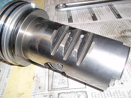
Close up of the valve body.
|
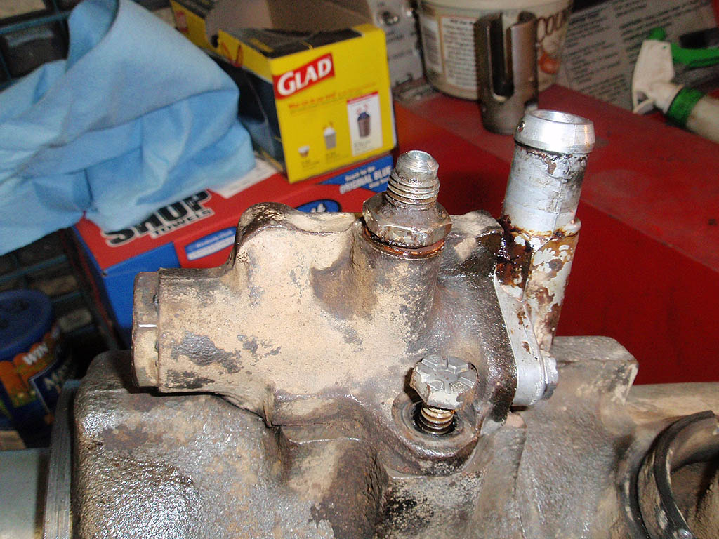
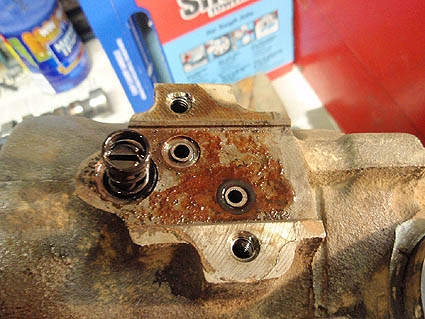 Top of steering box with valve body removed. Notice the O-rings. They are usually the source of leaks. Mark the valve body before removing, or the car may self steer to the left or right.
|

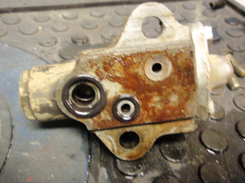
The bottom of the valve body with the other two O-rings.
|
 The return port removed showing two more O-rings.
|
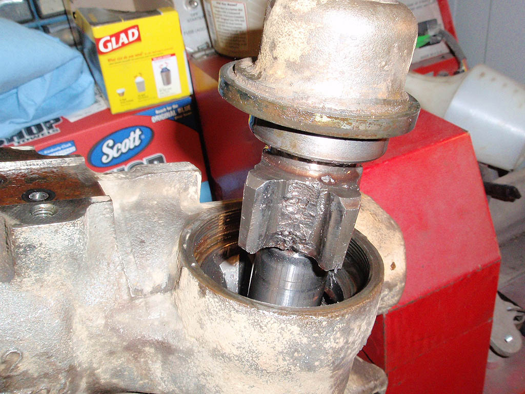
 Sector shaft partially removed. The special nut holding this and the internal parts in can usually be removed with a blunt chisel and a hammer. The center tooth is broken off on this one and the box will not be going back together. The 59 Imperial that this was in had suffered an accident on the right fender, and was likely hit on the wheel also. Surprisingly enough, this car still steered, although there was a lot of play in the wheel.
|
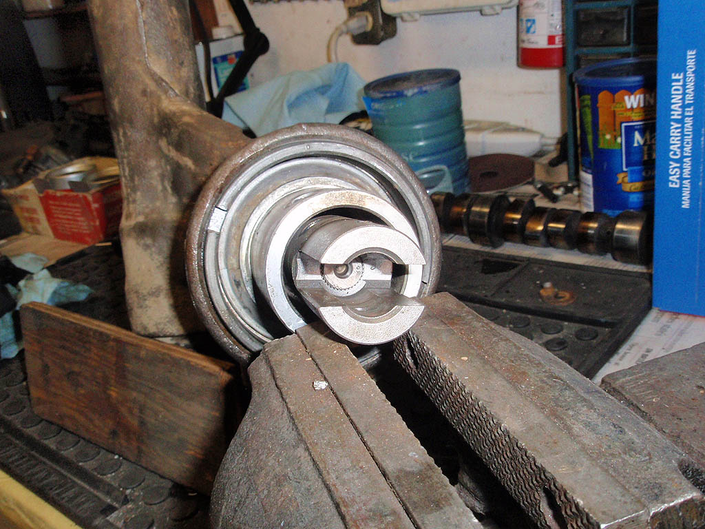
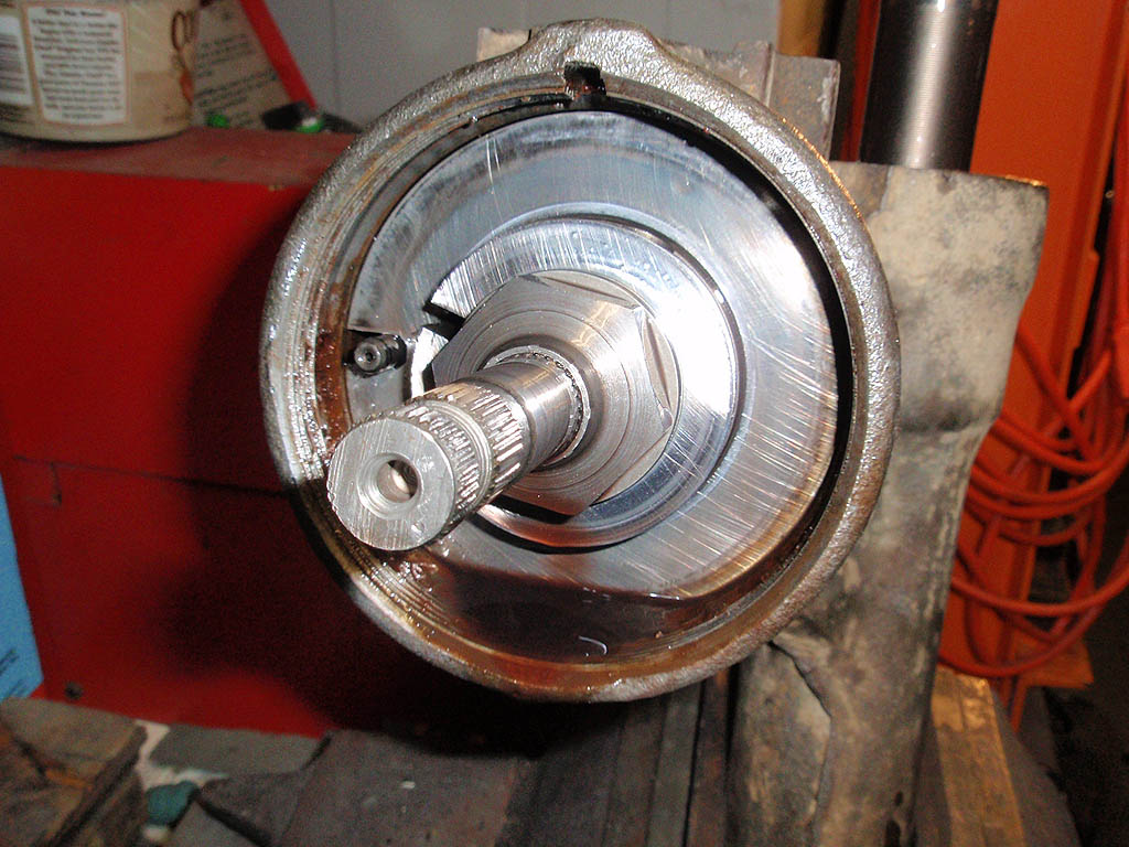
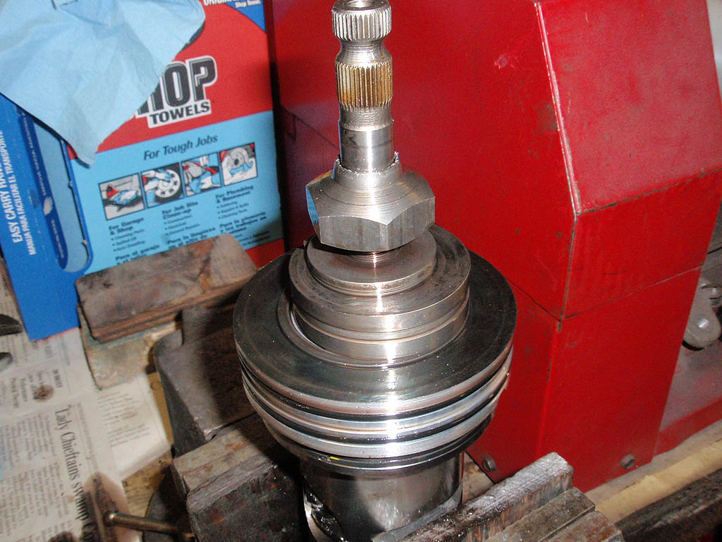
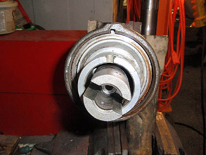 The steering shaft end of the box. The coupler is just there to center the sector shaft so it could be removed. The nut has been removed and the collar is ready to come out.
|

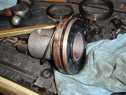
Collar removed showing lock nut for thrust bearing. If I was just re-sealing this box, everything would come out together to keep all the parts in line.
|
Collar removed showing upper sealing O-ring.
|
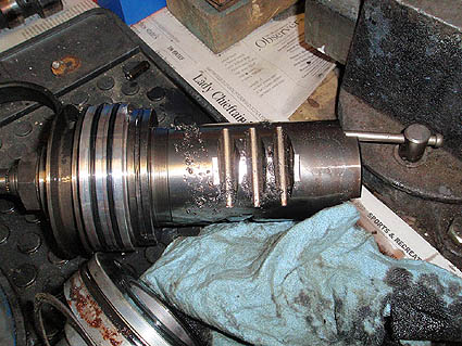
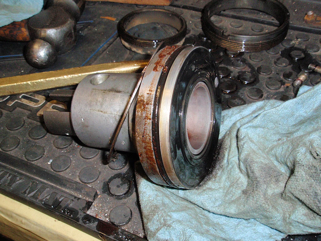
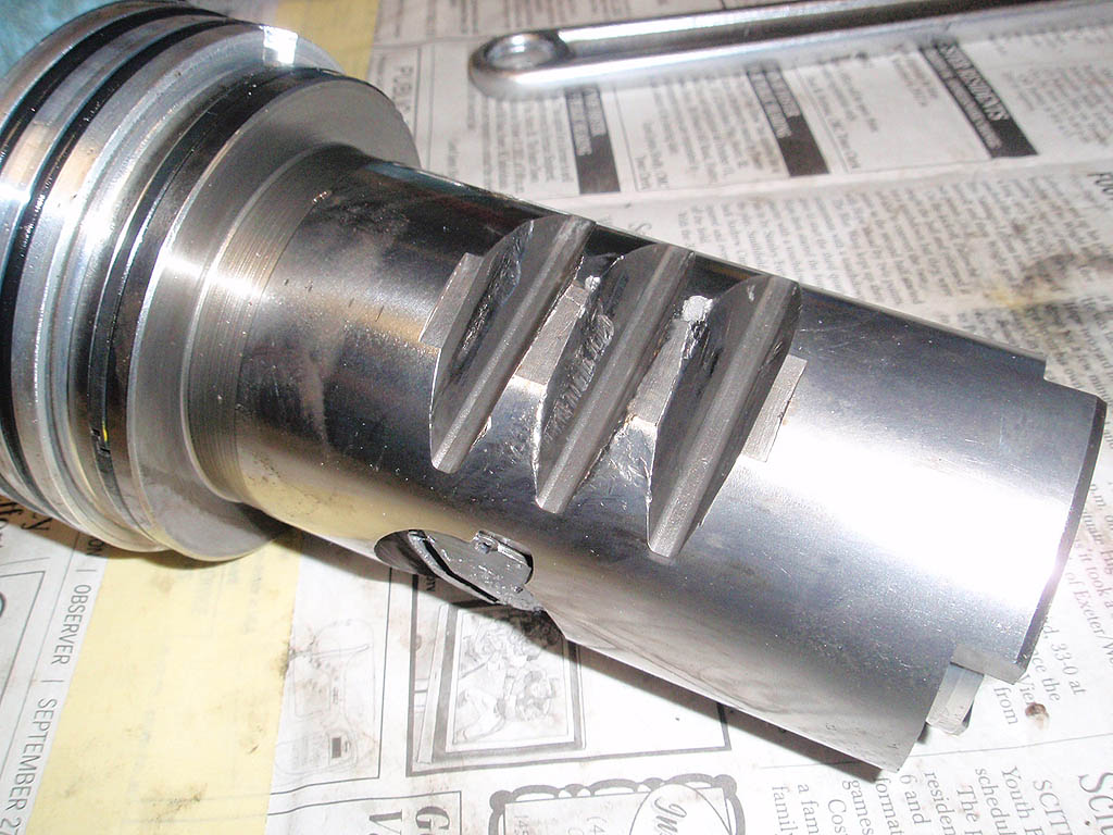
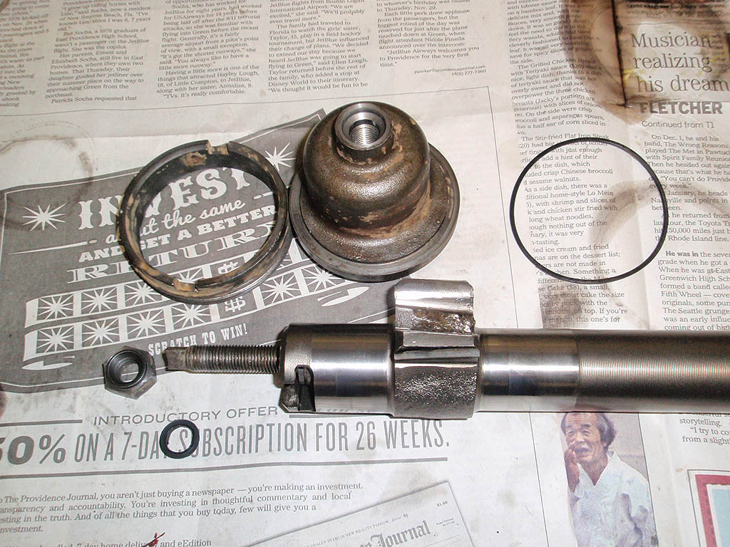
Worm shaft and ball housing along with internal valves removed. The teeth were badly worn on this also.
|
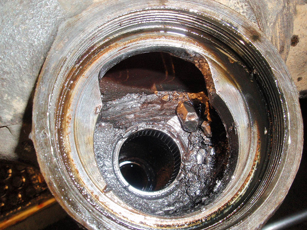
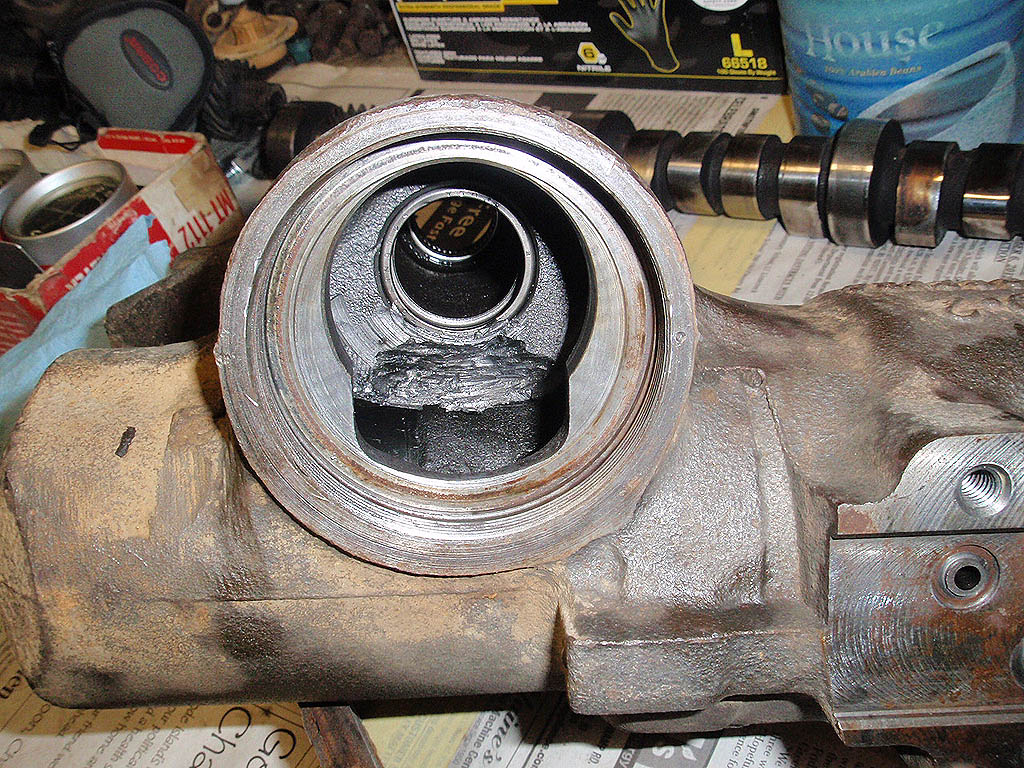
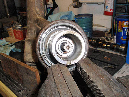
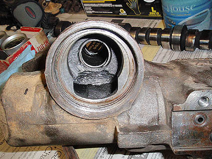
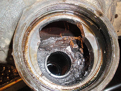 The view down in the housing showing the broken bits of gear teeth and the wear into the housing.
|

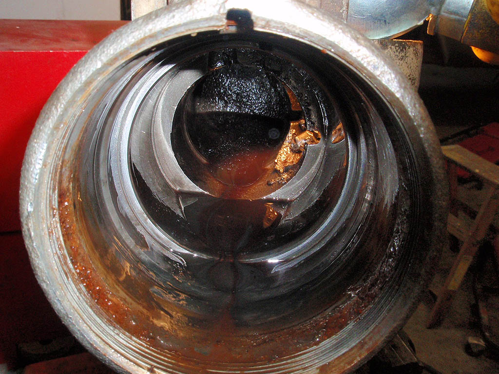
The view from the other end.
|
 Clamped in the vice to remove the thrust bearing lock nut. The nut is already loosened here.
|
Close up of wear on the teeth.
|
 Clean housing showing wear inside.
|

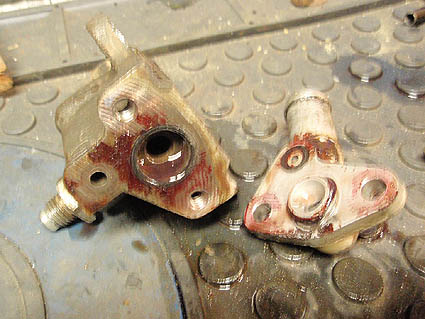
Valve body parts
|
 Sector shaft with adjuster nut, cover, and retaining nut.
|
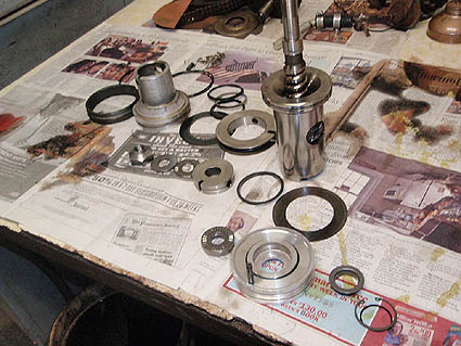
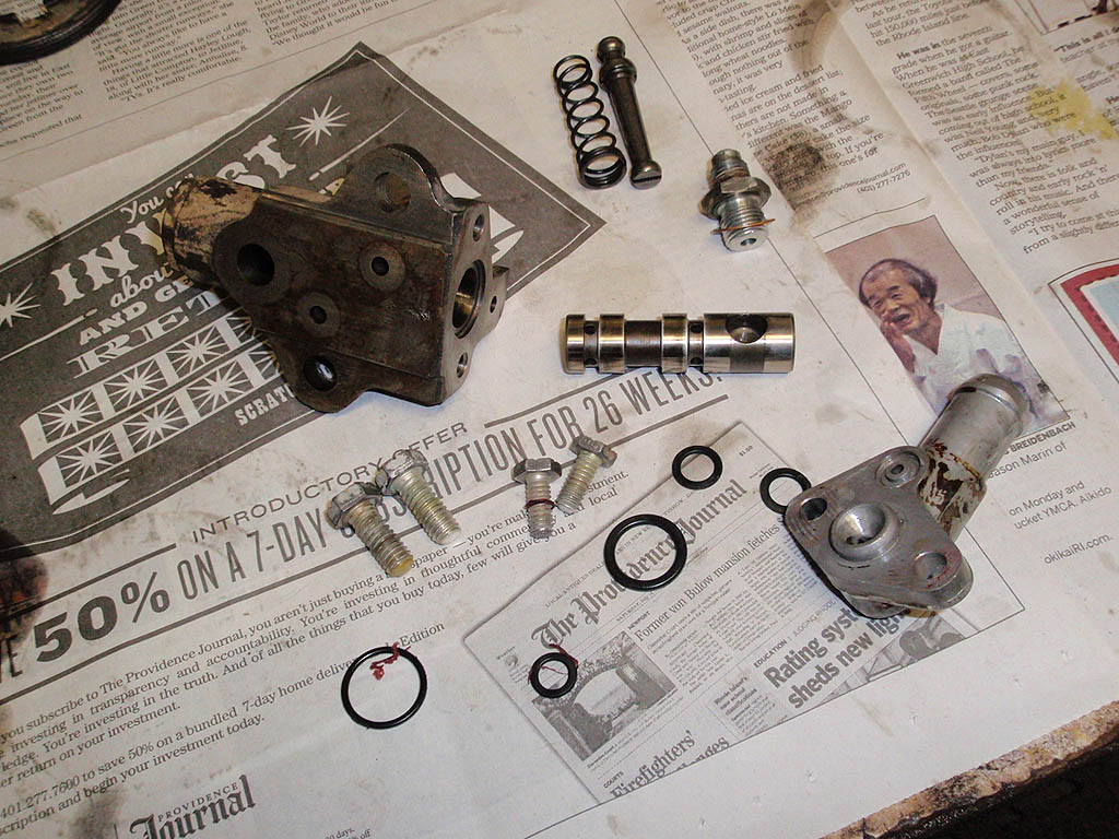
The rest of the internal parts basically lined up as they go together.
|