Cast-Iron Torqueflite Transmission- Disassembly and Reassembly Pictures
by Don Verity
Commonly referred to as the "Cast Iron Torqueflite" this transmission was use from 1956 through 1961.
This series of pictures is not intended to be a "how to" on torqueflite transmission overhaul. It is meant to give viewers an idea of what is inside their transmission, to take some of the mystery out. Overhauling one of these is best left to professionals.
300ly,
Don
How to use this page: please click on the Pic # at the beginning of each line to view the appropriate picture; then, just use the "back" function of your browser to return to this page.
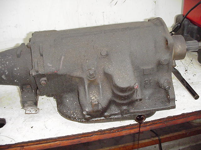
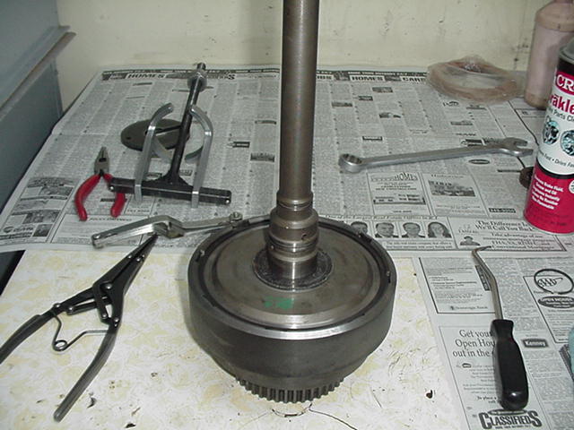
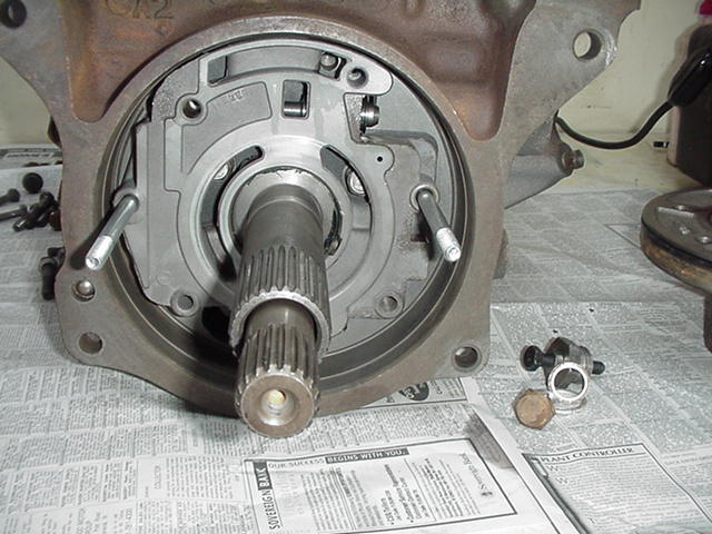
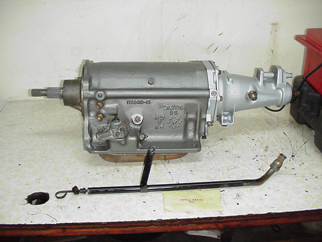
- Pic 1 Transmission ready for disassembly.
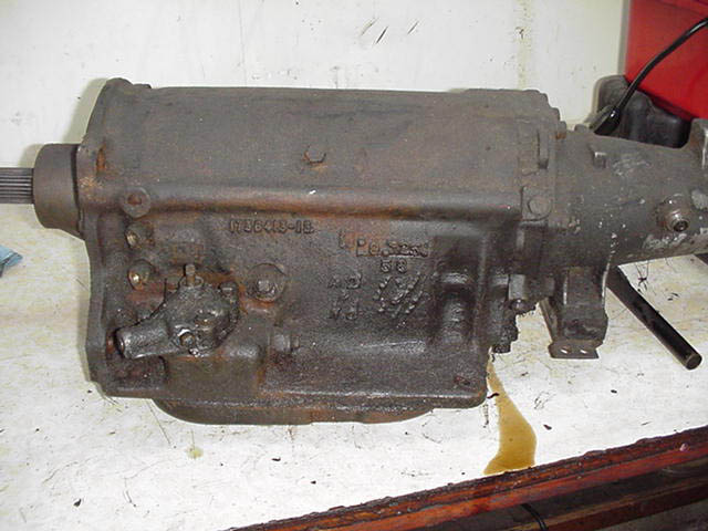
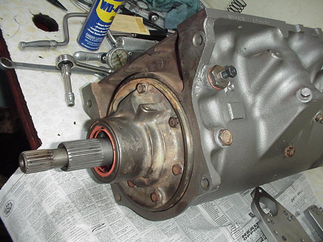
- Pic 2 Left side of trans. Line pressure port is right below cooler line fittings. Front band adjusting screw is above neutral switch.
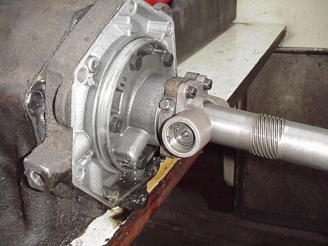
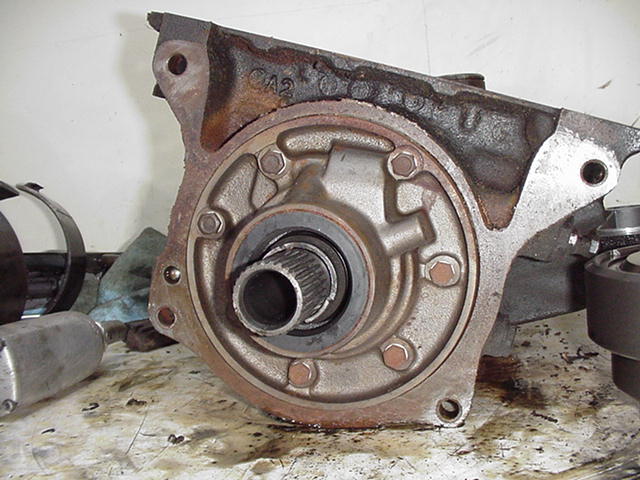
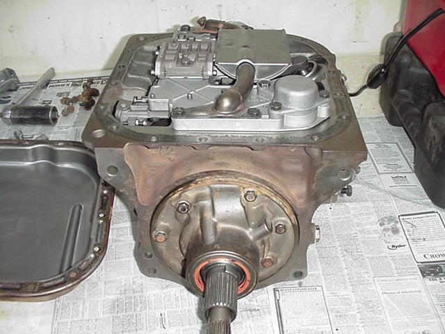
- Pic 3 Rear of trans with extension housing removed showing governor and rear pump housing.
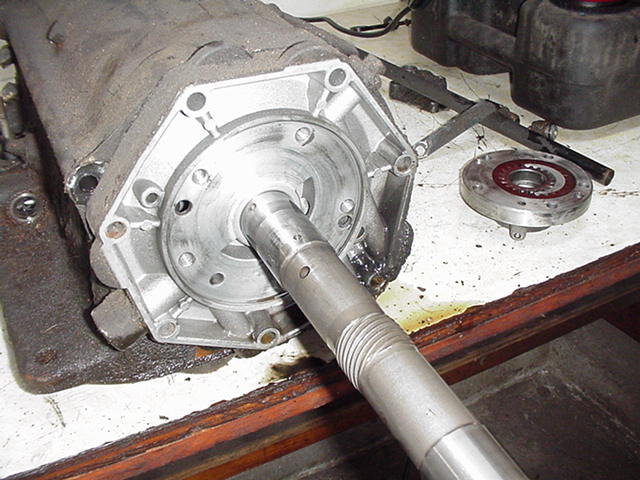
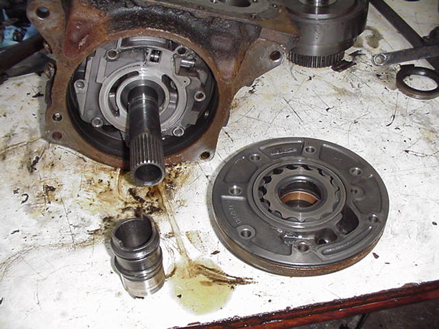
- Pic 4 Rear view with rear pump assembly to the right of picture. Surface that the pump gears ride on can be seen. This is a common wear area. This one is in good shape with only minor wear marks.
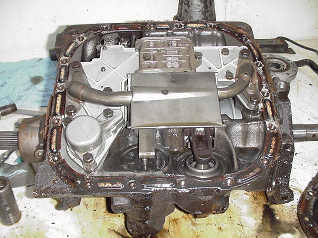
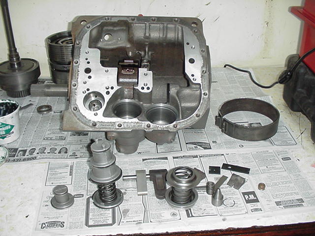
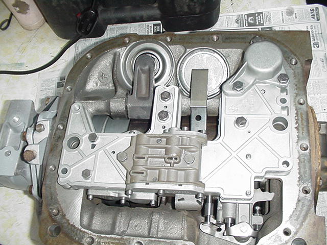
- Pic 5 Bottom view with oil pan removed showing filter screen and valve body. In foreground from left to right are the accumulator, front servo, and rear servo.
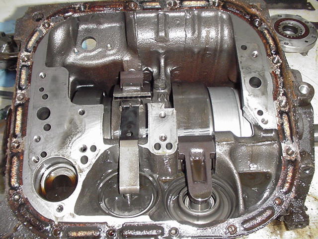
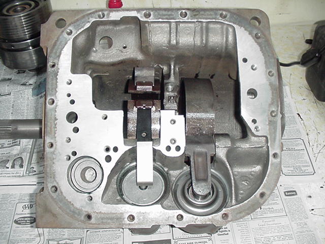
- Pic 6 Valve body removed. Now you can see the accumulator bore and the kickdown and reverse bands (left to right). Larger holes in the front and rear of the case are the oil pump intakes.
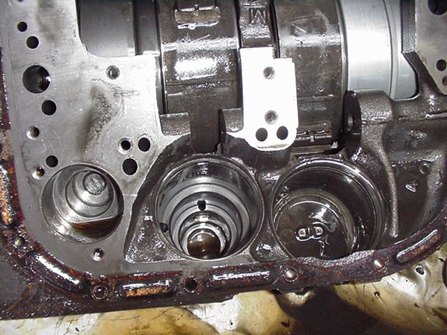
- Pic 7 Servos and accumulator piston removed.
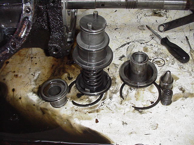
- Pic 8 Left to right: accumulator piston, front servo (kickdown), and rear servo (reverse).
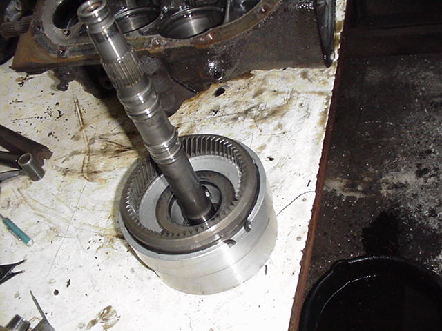
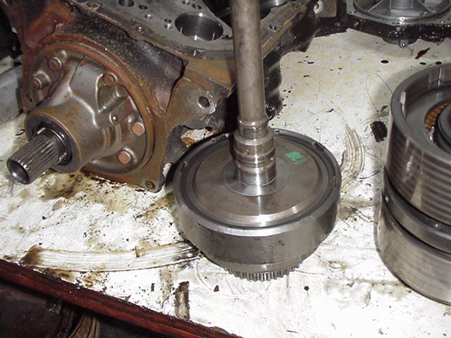
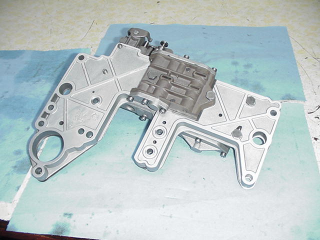
- Pic 9 Output shaft support and unit (assembly) number 1 removed from case. There is a hole in the bench that the front part of the unit is protruding through.
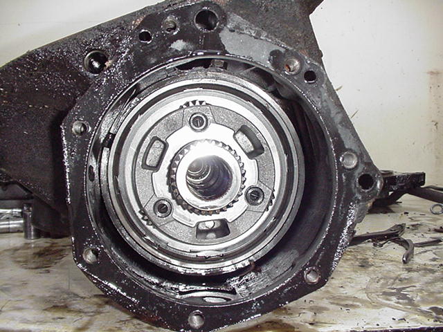
- Pic 10 Rear view of case with output shaft support and unit #1 removed.
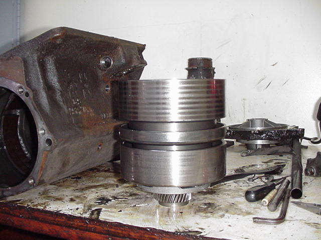
- Pic 11 Unit #2 removed from case. Three bolts hold the center support to the case, 2 external and one internal. Output shaft support can be seen to the right and rear of unit #2.
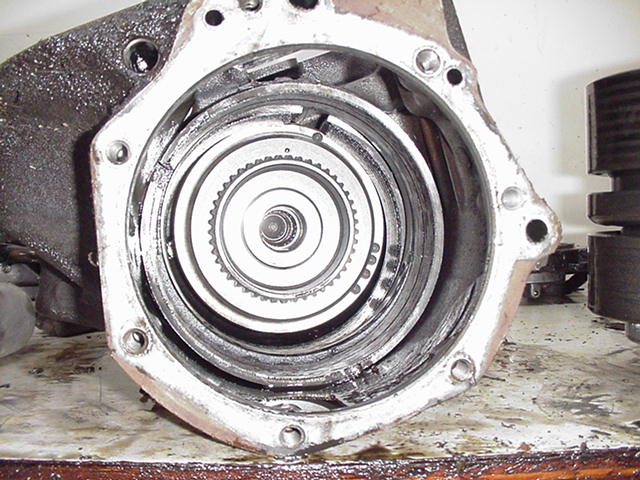
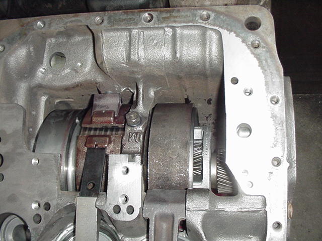
- Pic 12 Rear view with unit #2 removed. The low-reverse band can be seen in this picture.
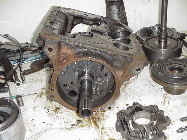
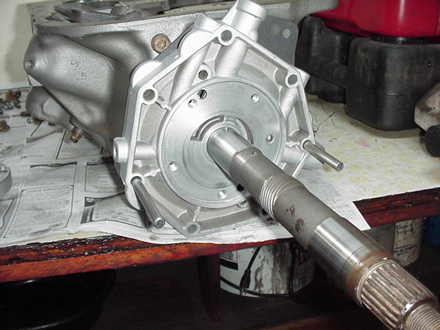
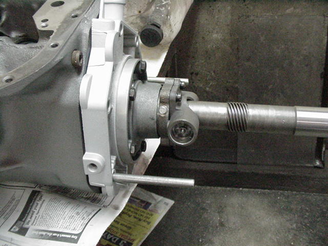
- Pic 13 Unit #3 removed (front clutch) and trans turned around showing front pump.
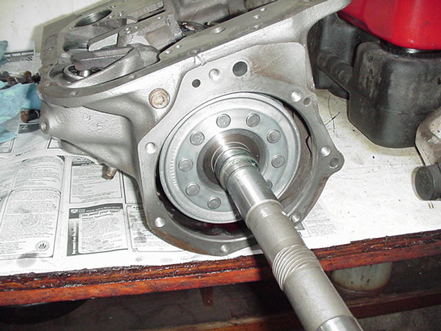
- Pic 14 Close up of front pump. Front seal, and drive sleeve can be seen.
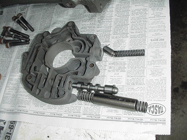
- Pic 15 Front pump removed with drive sleeve on the left and pump assembly on the right. Regulator valve body is still in trans case.
- Pic 16 Regulator valve body with main pressure regulator valve in front and torque converter control valve in rear.
- Pic 17 Empty trans case with dirty parts everywhere.
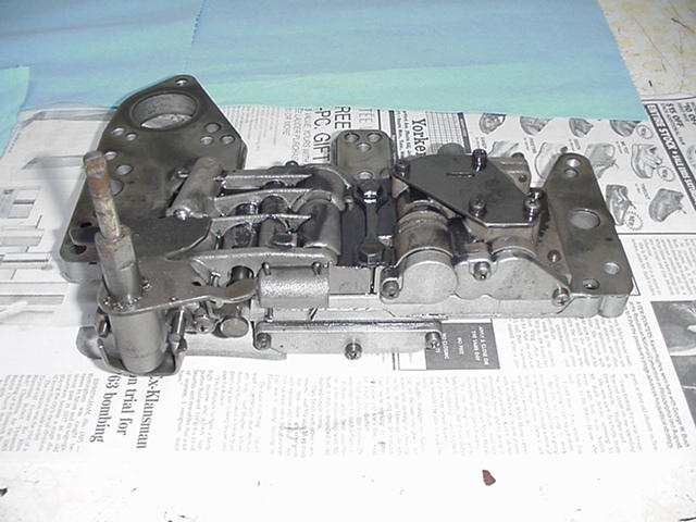
- Pic 18 The "brain" of the trans, the valve body.
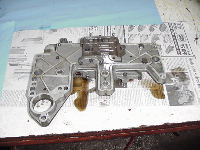
- Pic 19 Bottom side of the valve body.
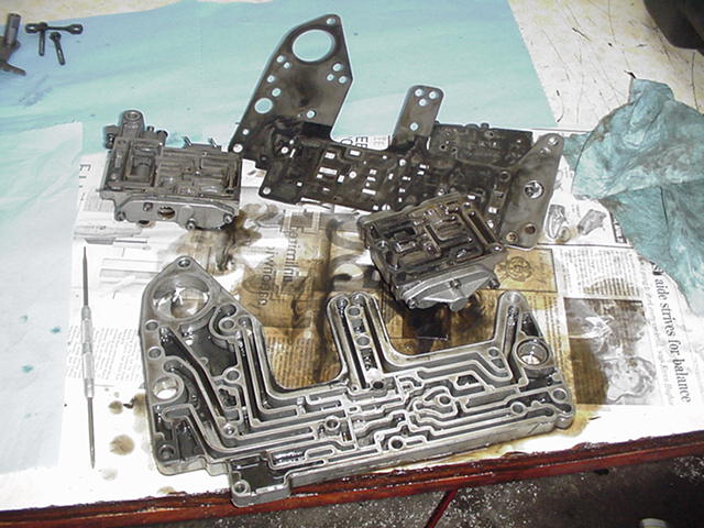
- Pic 20 Main pieces broken down into sub-assemblies. There is a lot of crud that hides in these things!
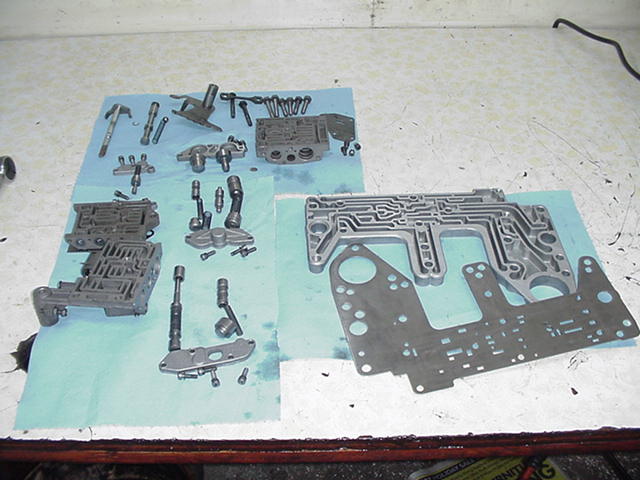
- Pic 1a Valve body parts cleaned and laid out for re-assembly.
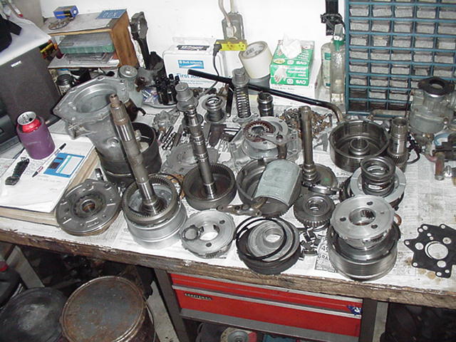
- Pic 2a All these parts are inside your transmission!
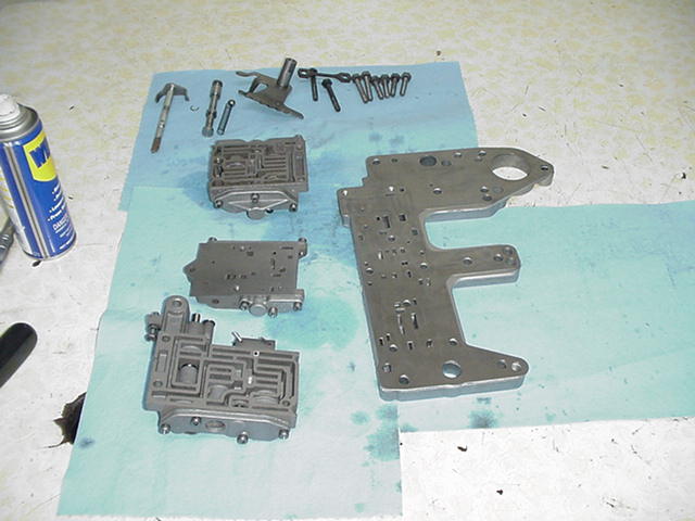
- Pic 3a Valve body sub-assemblies back together.
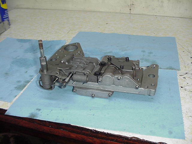
- Pic 4a Completed valve body top view.
- Pic 5a Completed valve body bottom view.
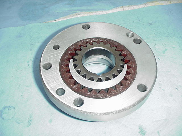
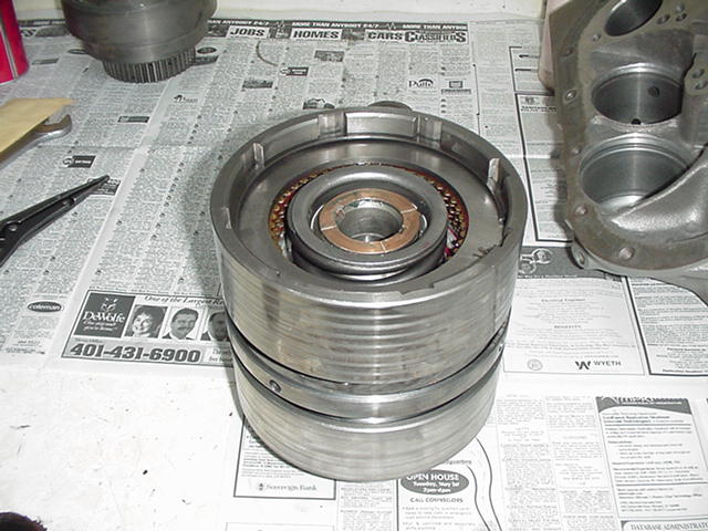
- Pic 6a Over-running clutch and front planetary components.
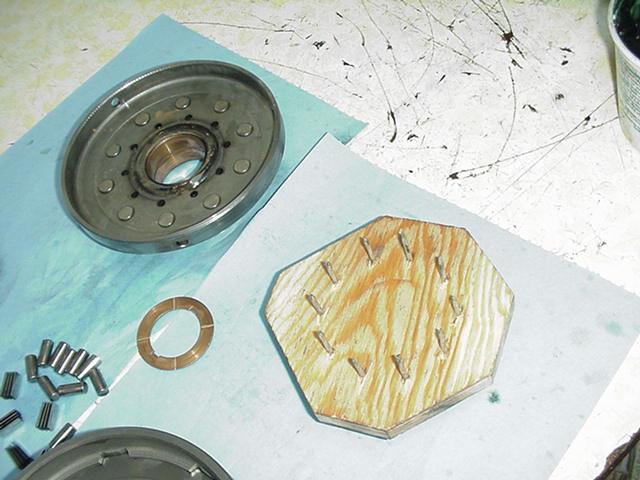
- Pic 7a Intermediate support, and home made special tool for installing clutch rollers and springs.
- Pic 8a Rollers and springs installed with tool still in position.
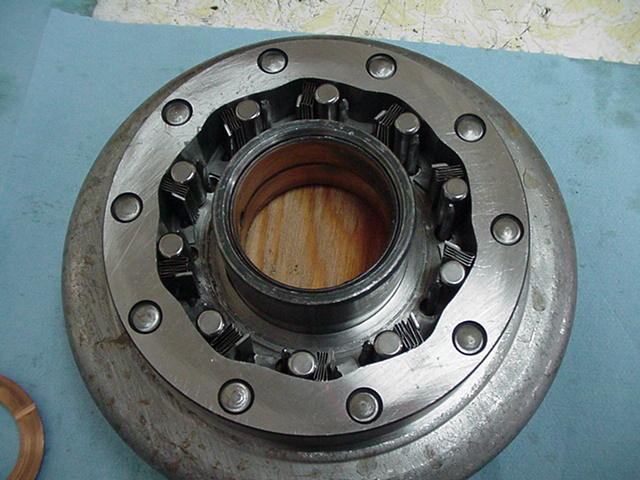
- Pic 9a Other side with tool removed. The rollers can be seen through the small holes.
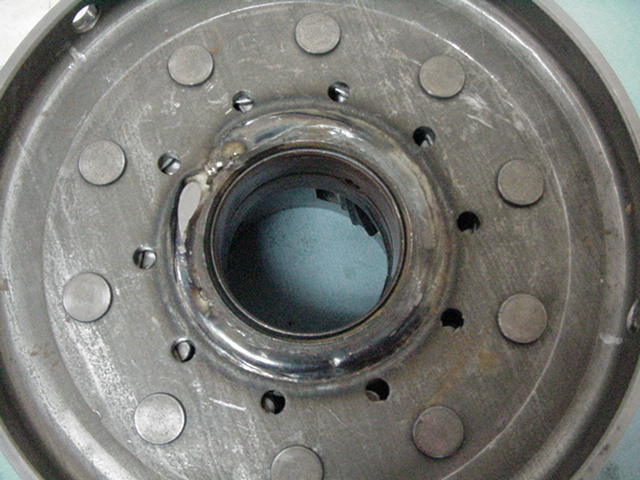
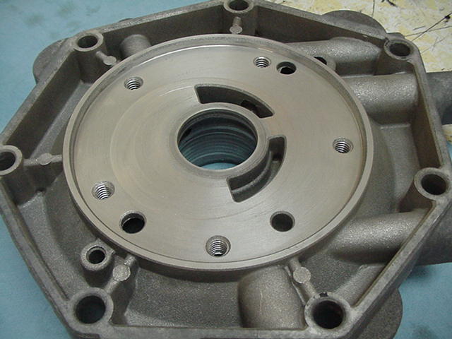
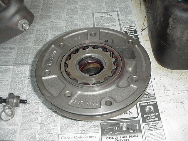
- Pic 10a Output shaft support showing machined surface that rear pump gears ride on. Very good condition.
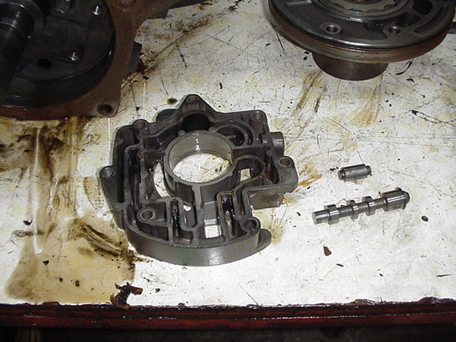
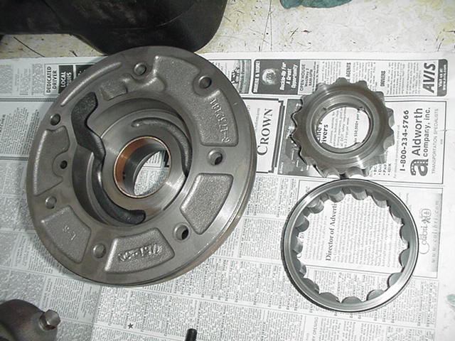
- Pic 11a Rear pump housing minus gears. Also showing minimal wear. Most are worn out from dirt in the fluid.
- Pic 12a Rear pump assembly
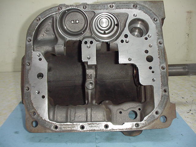
- Pic 13a Clean case, bottom view.
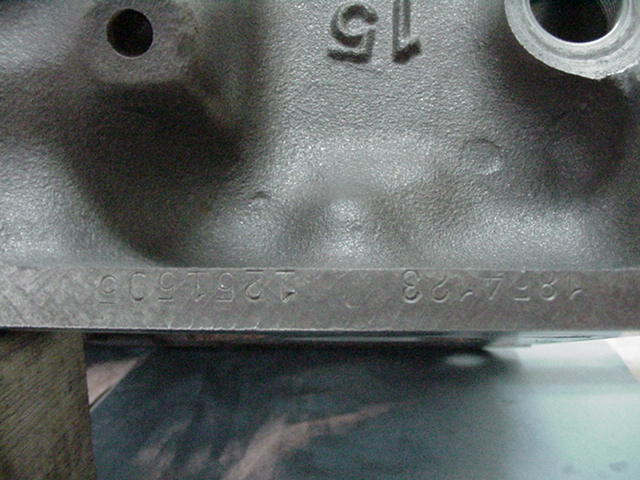
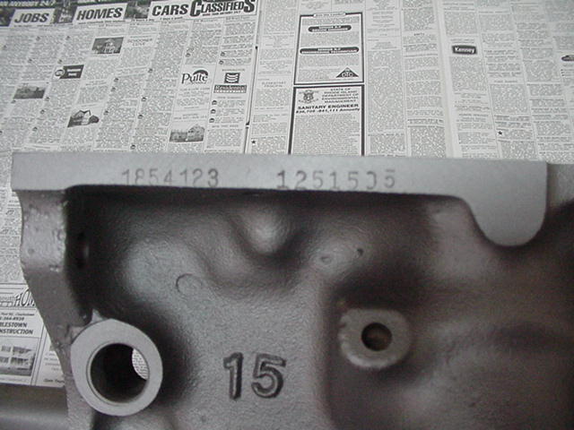
- Pic 14a Serial numbers on right pan rail.
- Pic 15a Clean case top view.
- Pic 16a Better view of serial number with case painted. This is a 300 transmission, 56-58.
- Pic 17a Front clutch components showing burnt clutch pack.
- Pic 18a Unit #1 components.
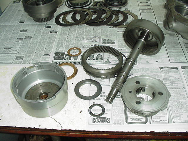
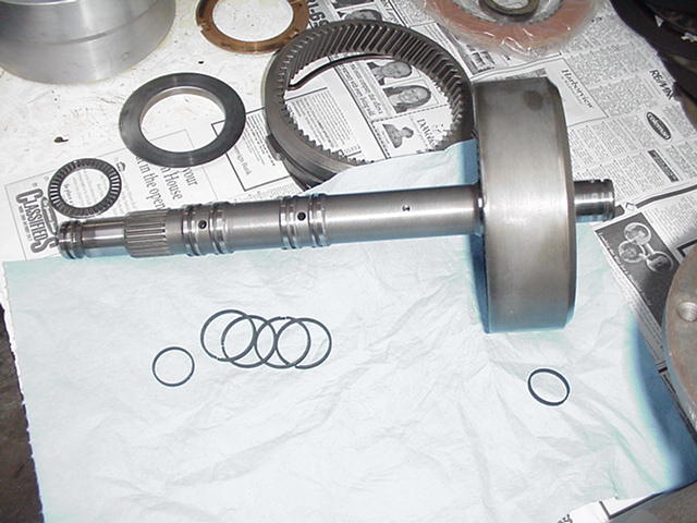
- Pic 19a Intermediate shaft with sealing rings and bearings.
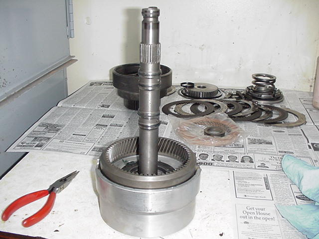
- Pic 20a Unit #1 assembled and ready to install.
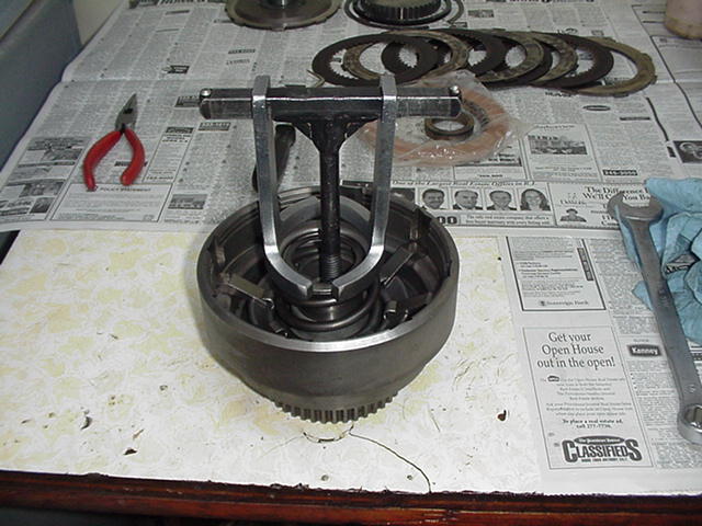
- Pic 21a Front clutch piston and components installed with compressor on top.
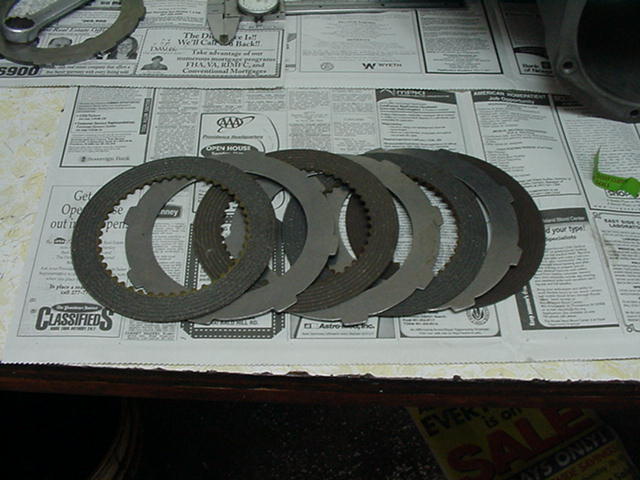
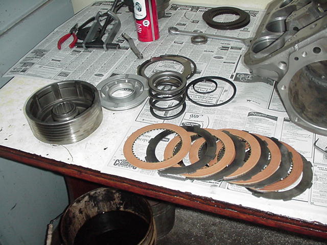
- Pic 22a New front clutch friction and steel plates.
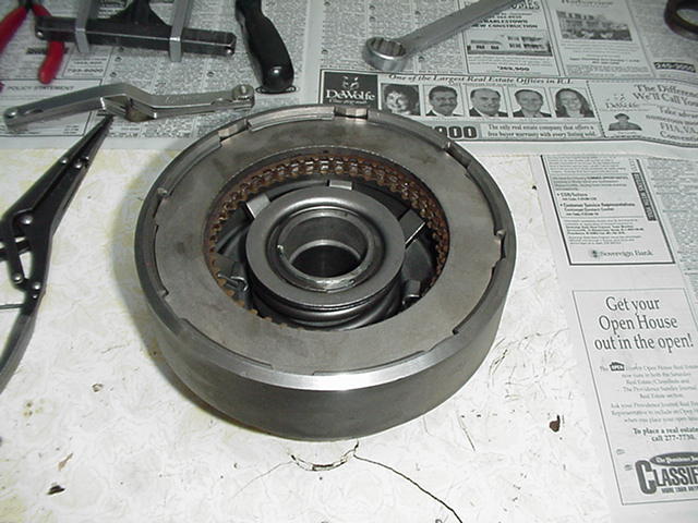
- Pic 23a Clutch plates installed with truck pressure plate temporarily installed to check clutch pack clearance.
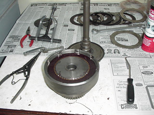
- Pic 24a Clutch pack with input shaft in the background.
- Pic 1b Assembled front clutch.
- Pic 2b Rear clutch components with new friction discs
- Pic 3b Unit #2 assembled with rear clutch on top.
- Pic 4b Servo parts ready to install into case. Front band is already in case, rear can be seen to the right. Units 2&3 in the background.
- Pic 5b Servos and bands installed.
- Pic 6b Units 2&3 installed. One of the center support lock bolts can be seen in the middle of the picture.
- Pic 7b Unit #1 installed. Extreme care must be used to avoid breaking sealing rings as the unit is installed.
- Pic 8b Output shaft support installed with guide studs visible.
- Pic 9b Rear pump and governor installed.
- Pic 10b Regulator valve body and components ready to install.
- Pic 11b Front pump body and gears, also in very good shape.
- Pic 12b Pump gears installed.
- Pic 13b Regulator valve body installed with spring retainers to the right.
- Pic 14b Front pump installed. Torque converter control valve spring retainer and pressure regulator spring retainer with adjuster can also be seen.
- Pic 15b Lower view with valve body installed.
- Pic 16b Completed transmission without pan.
- Pic 17b Completed transmission ready to install!
Please click HERE to go back to the Tech List !