The unusual instrument panel mounted turn signal system.....
have you ever wondered what parts and pieces make it work?
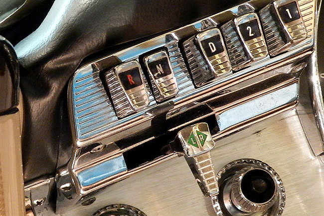
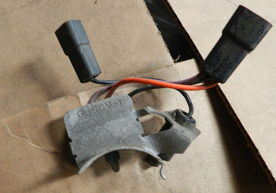
from the panel you would see this:
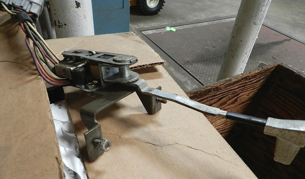

The switch has wires out the back and the lever moves a switch slider for left and right.
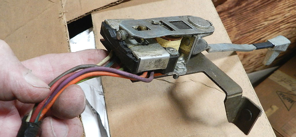
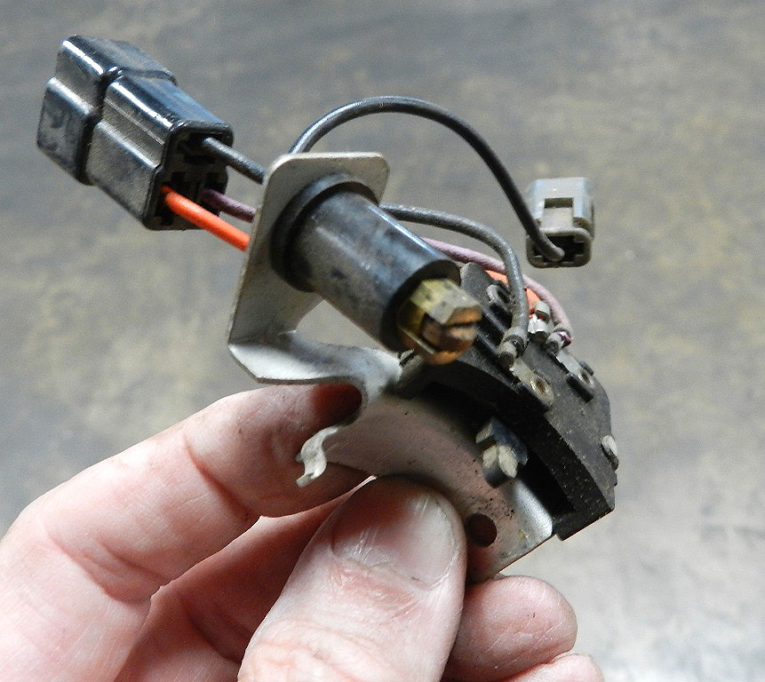
While that is easy enough to understand, complicating the device is some sort of wire coil.
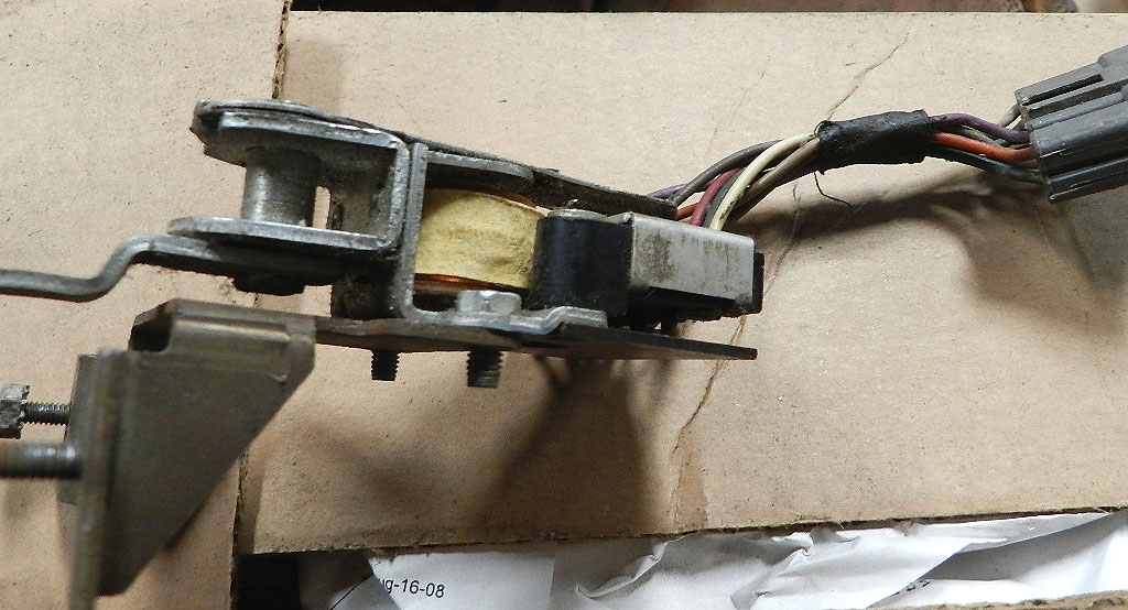
That is the electromagnet which holds the switch lever in the
left or right position while the turn signals are operating.
When the turn signals are deactivated by turning the steering wheel in the reverse direction,
the electromagnet is turned off and the switch lever
returns to the center position.
That means we need a switch to turn things off; a turn signal cancel switch.
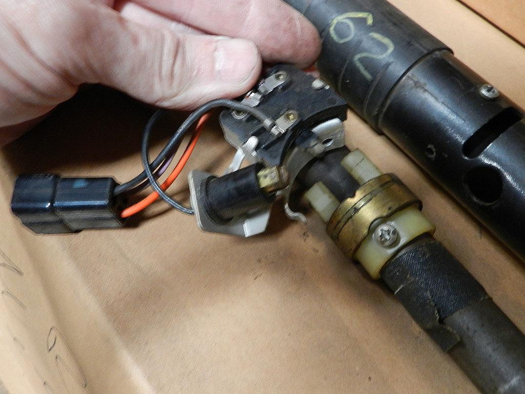
We find the cancel switch on the steering column, about half way down to the floor.
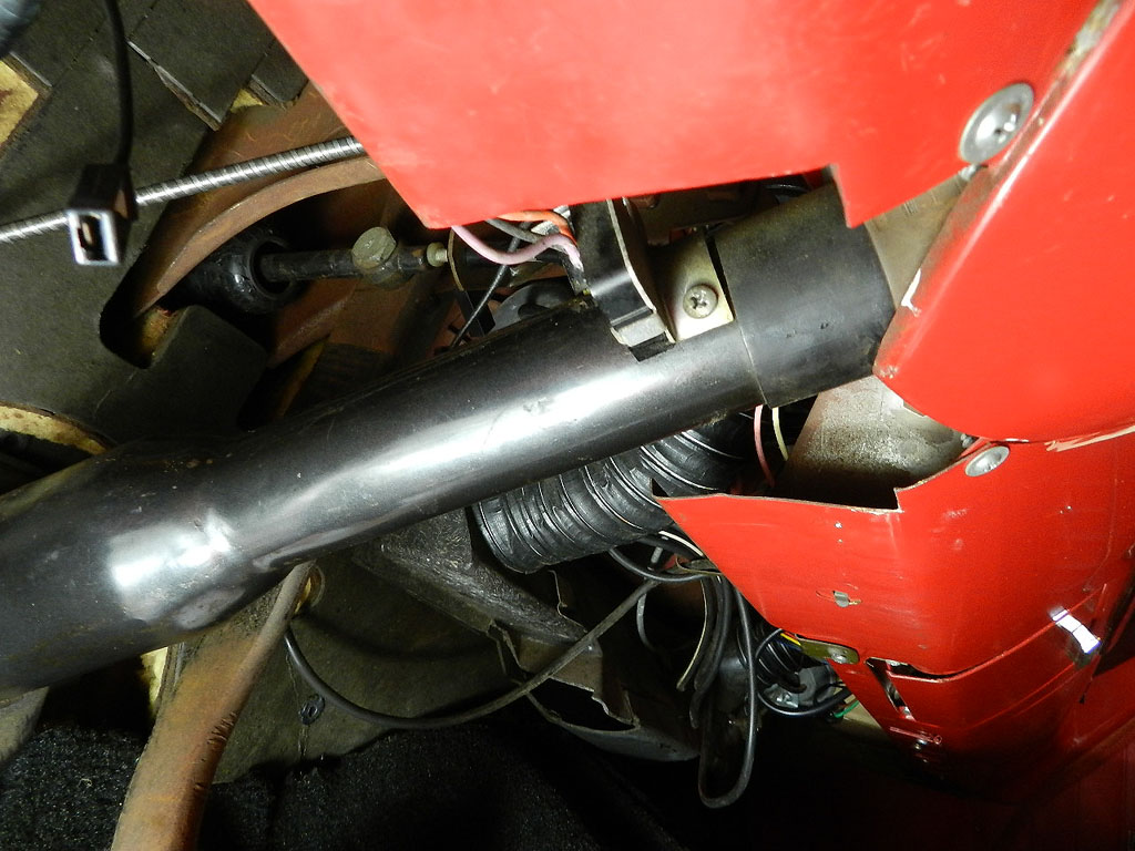
In this picture the steering column has been disassembled for clarity.
The cancel switch is mounted on the column and has two wire connectors attached to it.
One connector is for the turn signal cancel. The other is for the horn switch.
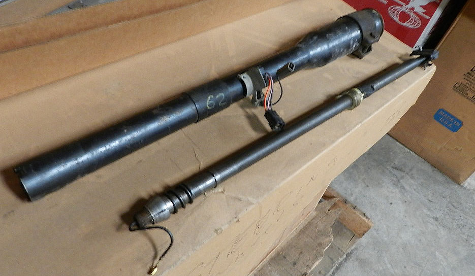
There are two things to notice in this picture --
the wheel connector for the horn and the prong for the cancel switch.
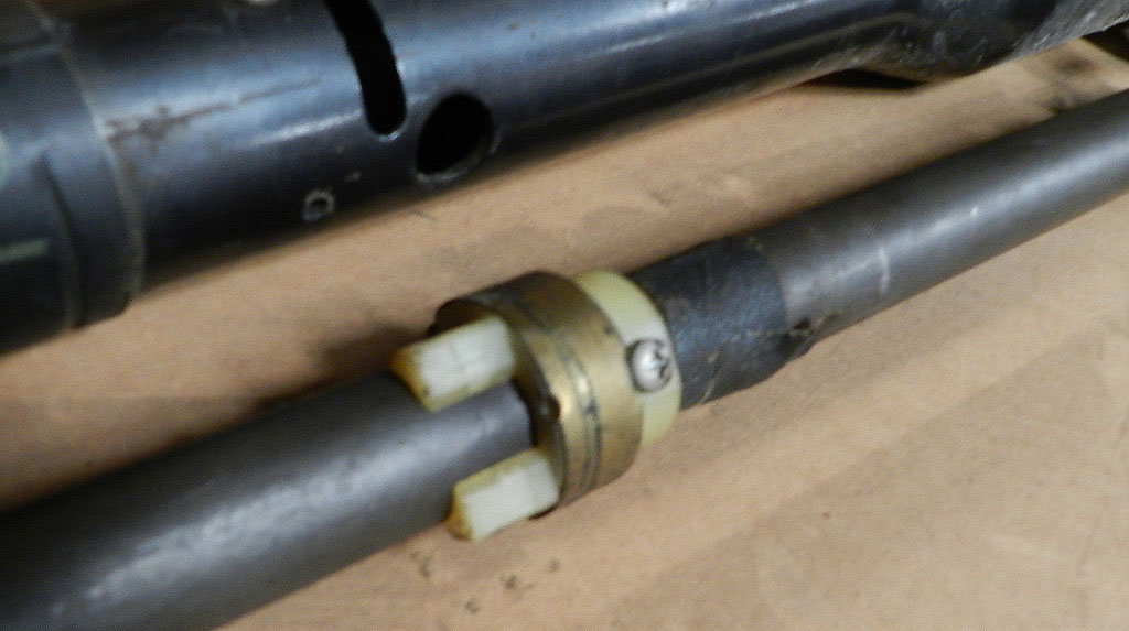
The steering column shaft has a brass collar for the horn switch roller connection
and has plastic pieces to engage the turn signal cancel switch prong.
Turning the steering wheel allows the turn signal cancel switch to be tripped by the plastic pieces, turning off the electromagnet on the turn switch lever and closing the process.
The cancel switch gets a lot of use over the years and is generally the first thing to fail.
For an article on repairing the turn signal switch, see Lindsey Fuller's page at this location.