|
Wiring Diagrams and Electro-Mechanical Details by Rich Barber July 15, 2015
An
adjustable tilt-type steering wheel was first offered on Chryslers in
1964 and was outsourced from the Saginaw Steering Gear Division of
General Motors. The adjustable steering wheels are mechanically and
electrically similar to the tilt columns of many GM products of the
mid 60’s and later. The steering wheel itself is different
from and not interchangeable with the standard or deluxe steering
wheels of 1964 Chryslers with non-adjustable steering columns as each
has a different splined end of the steering shaft.
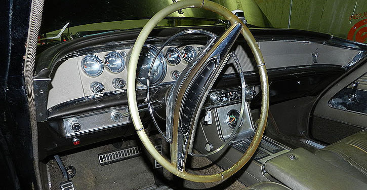
The 1964 Chrysler Pricing Information lists the “Steering Wheel, Adjustable” as Option Code #410, indicates it was available on all 1964 Chryslers with automatic transmission and power steering (including the Salon) and retailed for $46.65. The 1964 Chrysler Parts List indicates the color of the wheel was color-coded to the interior.
The switching of stop and turn signal lamps in the adjustable column take place in a manner different from that in the standard Chrysler column. In the standard column the switching takes place in the hub near the steering wheel requiring that a seven-wire extension be routed from the hub to a point on the lower column where the wires exit into a connector that mates to another connector with wires extending to various lamps and chassis looms. In the tilt column the switching takes place in a switch mounted at the lower end of the column with the switch position and function being controlled by a Bowden cable from the turn signal lever mechanism to the spring-loaded and adjustable-position switch. A separate wire from the horn switch is routed alongside of the Bowden cable from the hub to an exit point near the lower end of the column.
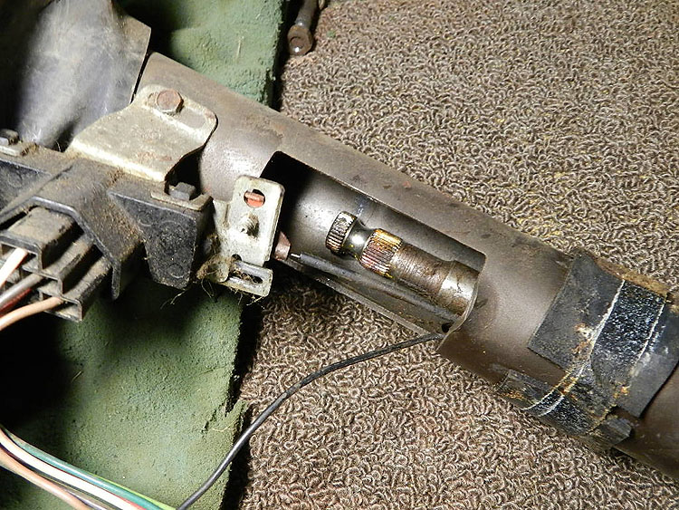
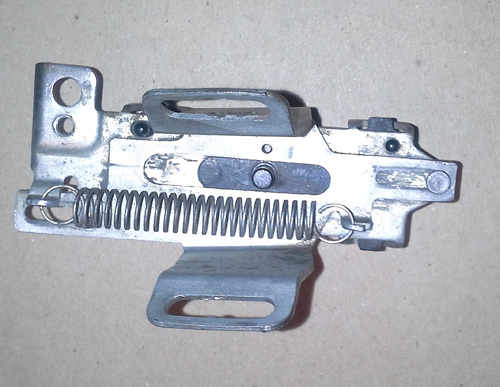
If the stiff central wire of the Bowden cable is broken it will have to be replaced. Reproduction cables are available in different lengths for GM vehicles such as Chevelles. Length of the Bowden cable is critical to proper operation of the switch. The switch itself consists of sliding brass contacts within the switch. Old and hard grease in the switch may prevent reliable electrical contact. The black plastic switch body may be removed from its steel mounting bracket, disassembled, cleaned, re-lubricated and reassembled with standard small tools and a careful eye for assembly details. The sliding portion of the switch glides on tiny ball bearings requiring careful disassembly over a container that will catch the tiny balls.
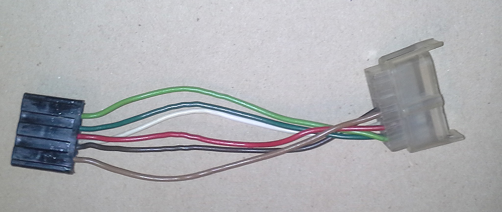
A special five-wire jumper with connectors on each end is used to interface the Saginaw column wiring to the Chrysler chassis wiring. The wiring diagrams show how this jumper connects the two systems. The wires in the jumper are the same the colors as the wires in the Chrysler loom to which they connect.
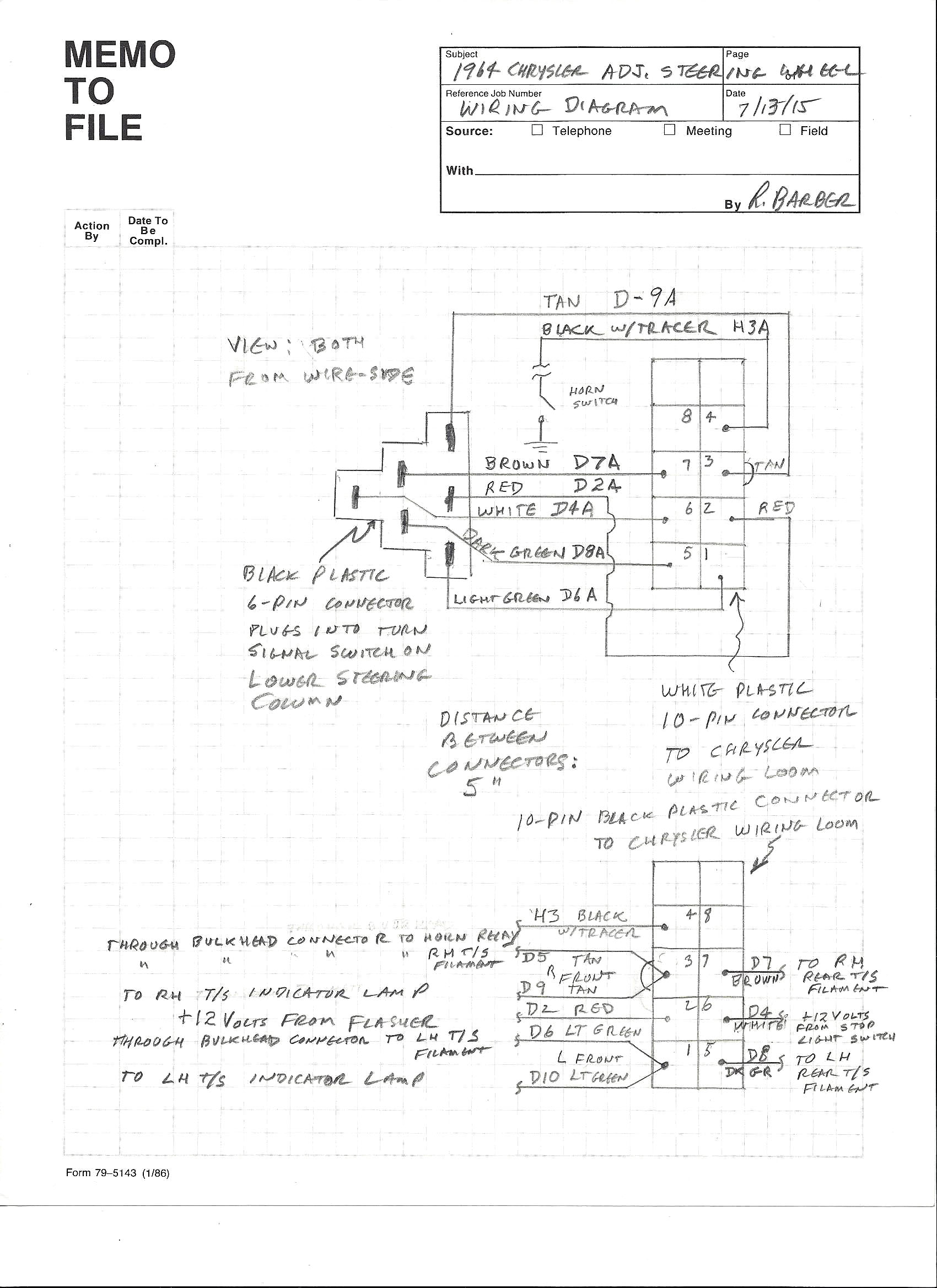
click to enlarge If any of the turn signals, stop lights or horn are not working properly, the system can be diagnosed by disconnecting the jumper from the chassis loom connector and touching connector spades 1, 3, 5 or 7 with a + 12 Volt probe. This should light up the LF & LIL, RF & RIL, LR & RR bulbs, respectively (LIL=Left turn indicator light on the dash—RIL the same, only the RH dash light). Failure to light a bulb indicates a problem with the bulb, its socket or the chassis or dash wiring. Touching spade 4 with a grounded probe should honk the horn. Attaching a Voltmeter probe to spade 2 should show + 12 Volts (from the flasher-with the ignition key “on”). Attaching the Voltmeter probe to spade 6 should show + 12 Volts when the stop light switch is closed by brake pedal pressure.
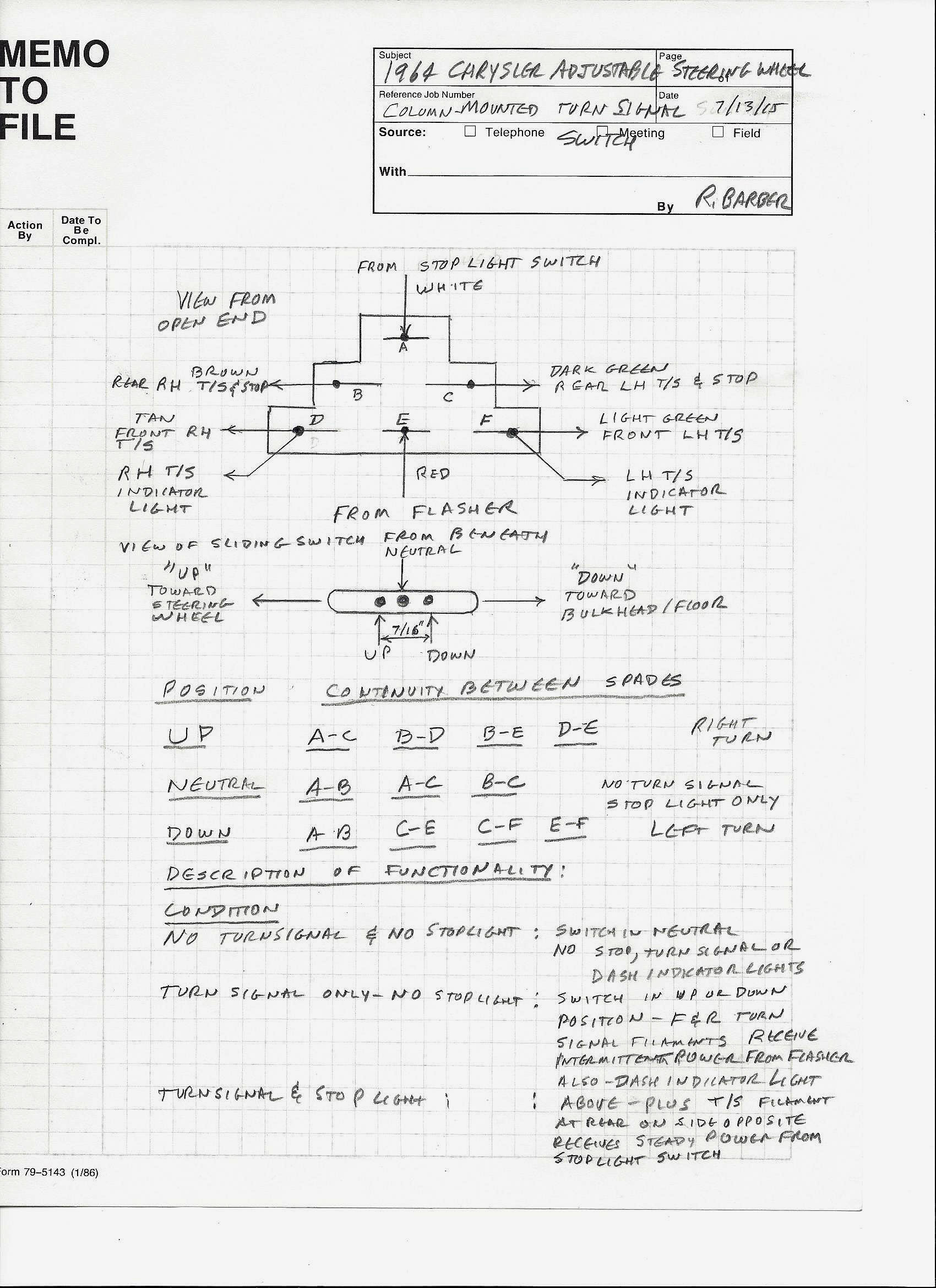
The
turn signal switch may be tested in or out of the car. In either
case, remove the jumper from the switch so the contact spades may be
accessed with a continuity tester. The attached drawing indicates
the proper continuity between spades of the switch as the black
plastic pin on the sliding portion of the switch is moved
approximately 7/32”-1/4” each way from its neutral
position or as the turn signal stalk is moved from one turn, through
neutral and to the other turn position.. Failure to establish
continuity over a narrow range of switch motion may indicate the need
for disassembly and internal cleaning of contacts.
Back to Tech Article Index |